Search for answers or browse our Knowledge Base.
Guides | Models | Validation | Blog
-
Guides
-
-
- Evaluating EMF Compliance - Part 1: A Guide to Far-Field RF Exposure Assessments
- Design Guidelines for Skeleton Slot Antennas: A Simulation-Driven Approach
- Simplified Modeling for Microstrip Antennas on Ungrounded Dielectric Substrates: Accuracy Meets Simplicity
- Fast Modeling of a Monopole Supported by a Broadcast Tower
- Linking Log-Periodic Antenna Elements Using Transmission Lines
- Wave Matching Coefficient: Defining the Practical Near-Far Field Boundary
- AN-SOF Mastery: Adding Elevated Radials Quickly
- How to Merge Projects
- On the Modeling of Radio Masts
- The Equivalent Circuit of a Balun
- AN-SOF Antenna Simulation Best Practices: Checking and Correcting Model Errors
-
-
- AN-SOF Antenna Simulation Software - Version 8.90 Release Notes
- AN-SOF 8.70: Enhancing Your Antenna Design Journey
- Introducing AN-SOF 8.50: Enhanced Antenna Design & Simulation Software
- Get Ready for the Next Level of Antenna Design: AN-SOF 8.50 is Coming Soon!
- Explore the Cutting-Edge World of AN-SOF Antenna Simulation Software!
- Upgrade to AN-SOF 8.20 - Unleash Your Potential
- AN-SOF 8: Elevating Antenna Simulation to the Next Level
- New Release: AN-SOF 7.90
- AN-SOF 7.80 is ready!
- New AN-SOF User Guide
- New Release: AN-SOF 7.50
- AN-SOF 7.20 is ready!
- New Release :: AN-SOF 7.10 ::
- AN-SOF 7.0 is Here!
- New Release :: AN-SOF 6.40 ::
- New Release :: AN-SOF 6.20 ::
- Show All Articles ( 1 ) Collapse Articles
-
-
-
-
Models
-
- Modeling a J-Fed 5-Element Collinear Antenna for the 2 m Band
- Simulating the Ingenious Multiband Omnidirectional Dipole Antenna Design
- The Loop on Ground (LoG): A Compact Receiving Antenna with Directional Capabilities
- Precision Simulations with AN-SOF for Magnetic Loop Antennas
- Advantages of AN-SOF for Simulating 433 MHz Spring Helical Antennas for ISM & LoRa Applications
- Radio Mast Above Wire Screen
- Square Loop Antenna
- Receiving Loop Antenna
- Monopole Above Earth Ground
- Top-Loaded Short Monopole
- Half-Wave Dipole
- Folded Dipole
- Dipole Antenna
- The 5-in-1 J-Pole Antenna Solution for Multiband Communications
-
- Extended Double Zepp (EDZ): A Phased Array Solution for Directional Antenna Applications
- Transmission Line Feeding for Antennas: The Four-Square Array
- Log-Periodic Christmas Tree
- Enhancing VHF Performance: The Dual Reflector Moxon Antenna for 145 MHz
- Biquad UHF Antenna Array
- 145 MHz 5-Element Array of Square Loops
- Broadside Dipole Array
- Log-Periodic Dipole Array
- Broadband Directional Antenna
- A Closer Look at the HF Skeleton Slot Antenna
- The 17m Band 2-Element Delta Loop Beam: A Compact, High-Gain Antenna for DX Enthusiasts
- Enhancing Satellite Links: The Moxon-Yagi Dual Band VHF/UHF Antenna
- Array of Snowflake Quads
-
Validation
-
-
- Simple Dual Band Vertical Dipole for the 2m and 70cm Bands
- Linear Antenna Theory: Historical Approximations and Numerical Validation
- Validating Panel RBS Antenna with Dipole Radiators against IEC 62232
- Directivity of V Antennas
- Enhanced Methodology for Monopoles Above Radial Wire Ground Screens
- Dipole Gain and Radiation Resistance
- Convergence of the Dipole Input Impedance
- Impedance of Cylindrical Antennas
-
Magnetic loop antennas find extensive application within the realm of amateur radio pursuits. One prevalent design employs a dual loop configuration, wherein a larger loop, equipped with a tuning capacitor at one end, is magnetically linked to a smaller loop positioned inside it. The smaller loop serves as the connection point for the coaxial cable, which feeds the antenna. This antenna’s construction is remarkably straightforward, as it capitalizes on the adaptability of coaxial cable wires for assembly. It is important to emphasize that the interplay between the two loops is rooted in induction rather than physical linkage.
Illustrated in the accompanying image, the simulation delves into an instance where the larger loop, fashioned from RG-8 cable, spans a diameter of 70 cm, while the smaller loop, crafted from RG-6 cable, boasts a 15 cm diameter. Maintaining a separation of 2 cm between the loops at the antenna’s base, the provided diagram outlines the requisite tuning capacitor settings for achieving resonance across five distinct frequencies: 3.5, 7, 14, 21, and 29 MHz.
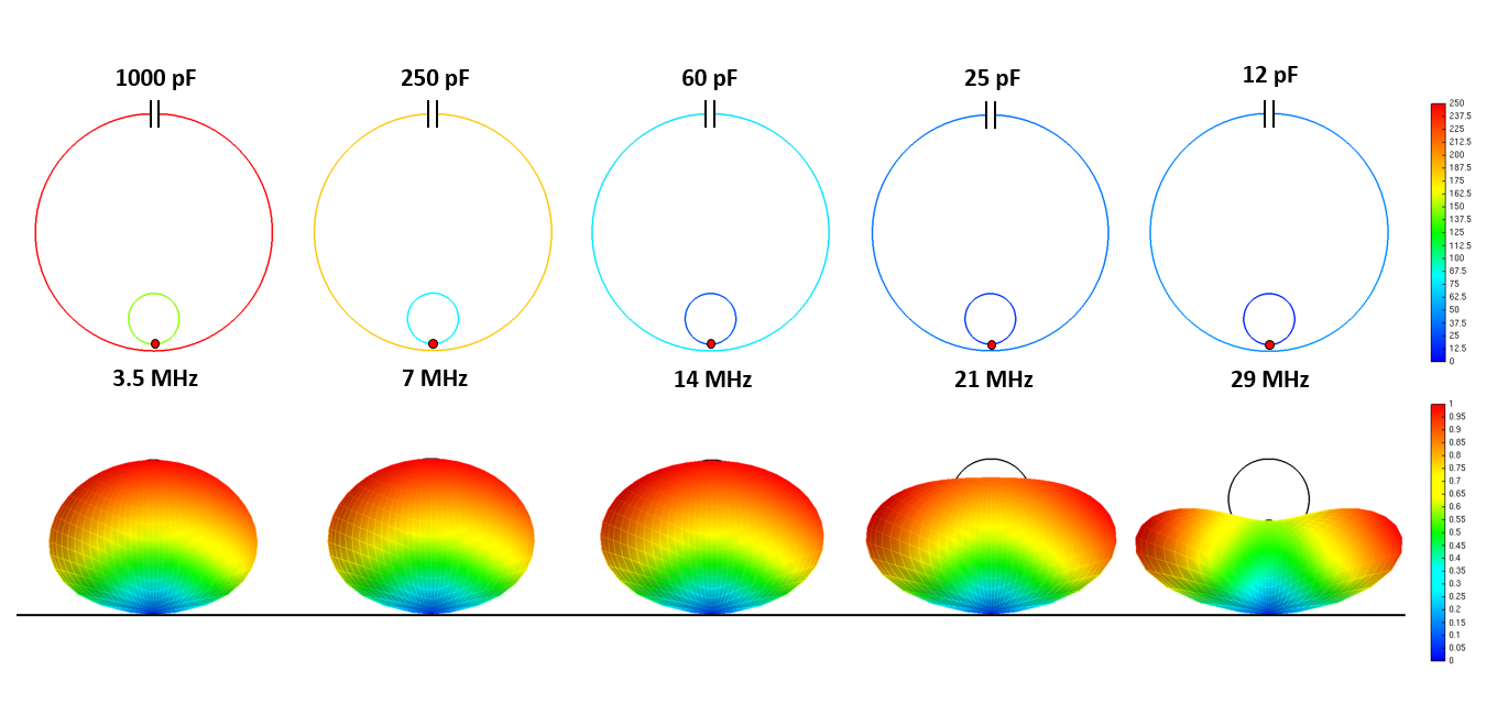
Sited a meter above a typical ground plane, the antenna showcases a radiation pattern that diverges from the conventional toroidal shape anticipated for a small loop positioned in free space. The color scale displayed on the loops indicates the current intensity corresponding to each resonant frequency.
Facilitating precise simulations of this antenna design, the AN-SOF Antenna Simulator leverages the Conformal Method of Moments featuring curved segments. This enables the meticulous replication of loop contours. A noteworthy attribute of AN-SOF lies in its use of an exact Kernel, which accommodates close proximity of both loops at the antenna’s base.
The simulator further streamlines the calculation process by permitting sequential and automated execution of the antenna’s resonance calculations across the five specified frequencies. This eliminates the need for manual execution of each calculation. To access this feature, navigate to the AN-SOF main menu and select Run Bulk Simulation under the “Run” category. This function allows you to effortlessly run calculations on the five “.nec” files, available for download via the provided button. Importantly, this functionality is available even with the trial version of AN-SOF.