Search for answers or browse our Knowledge Base.
Guides | Models | Validation | Blog
Enhancing VHF Performance: The Dual Reflector Moxon Antenna for 145 MHz
The Moxon antenna, or Moxon rectangle, represents a straightforward yet mechanically robust wire antenna meticulously crafted for VHF bands. It owes its name to the renowned radio amateur operator Les Moxon (call sign G6XN). This antenna comprises two folded dipole elements, one of which acts as the driven element, while the other serves as the reflector element. An adjustable gap is deliberately left between these folded dipoles, permitting fine-tuning of the antenna to minimize the VSWR (Voltage Standing Wave Ratio). Consequently, this antenna can be mechanically tuned, negating the necessity for an impedance matching network.
In our article titled “Enhancing Satellite Links: The Moxon-Yagi Dual Band VHF/UHF Antenna,” we introduce a dual-band design optimized for satellite communications. This design amalgamates a 5-element Yagi-Uda array with the Moxon configuration, leveraging the Moxon portion as the excitation point, while the Yagi section is electromagnetically induced for feeding.
In this article, we introduce a modified version of the Moxon antenna featuring two reflector elements, as depicted in the accompanying figure. These reflectors are oriented at an angle of 76° relative to each other. This particular configuration delivers a notable reduction in the beamwidth within the plane of the driven element (the vertical plane denoted as y-z in the figure), resulting in a corresponding increase in gain.
To optimize the performance of this antenna, the gaps have been meticulously adjusted to achieve an input impedance of 47 Ohms precisely at the resonance frequency of 145 MHz, eliminating the need for an external matching network. The key characteristics and outcomes of this antenna design are summarized below:
- Resonance Frequency: 145 MHz
- Input Impedance: 47 Ohms (self-resonant)
- Bandwidth: 7% (VSWR < 2)
- Peak Gain: 6.3 dBi
- Front-to-Back Ratio: 19 dB
- Beamwidth: 130° Horizontal / 80° Vertical
- Polarization: Vertical
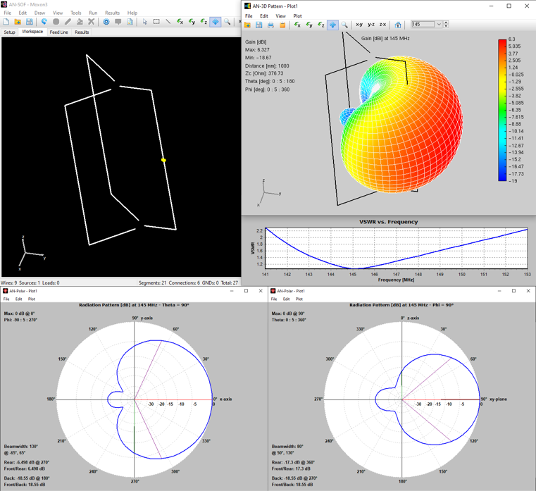
As depicted in the figure below, we present the antenna model as simulated using the AN-SOF Antenna Simulator. The three-dimensional radiation pattern is illustrative, showcasing a peak gain of 6.3 dBi. Additionally, the VSWR curve is provided, and it is evident that the resonant frequency of 145 MHz corresponds to the dip in this curve.
Further insight is offered by the polar diagrams at the bottom of the figure, representing the horizontal (on the left) and vertical (on the right) slices of the 3D radiation pattern. These diagrams distinctly show that the vertical pattern is narrower in comparison to the horizontal pattern.
For amateur radio enthusiasts and practitioners, this antenna design serves as an excellent choice when there is a demand for a VHF-frequency directive antenna that is easy to construct, mechanically robust, self-resonant, and delivers outstanding performance.