Industry Solutions & Capabilities
The Precision Engine for Antenna Design
AN-SOF is a specialized simulation environment for the high-fidelity modeling and analysis of complex antenna systems. Built on the Conformal Method of Moments (CMoM) with Exact Kernel, it provides engineers and researchers with a numerically superior tool for validating designs before they reach the prototype stage.
From academic research to industrial RF engineering, AN-SOF provides the accuracy needed to bridge the gap between theoretical modeling and real-world performance.
Core Areas of Application
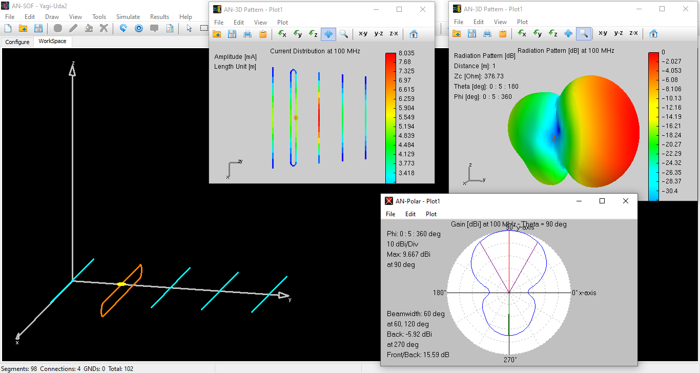
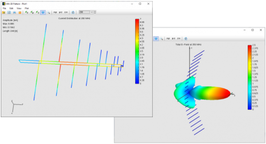
- Precision Wire Modeling: Dipoles, Monopoles, Yagi-Uda, and Log-Periodic arrays.
- Complex Geometries: Helices, Spirals, Loops, and Fractal antennas.
- Environmental Analysis: Modeling antennas above lossy ground planes and radial wire ground screens.
- Planar Structures: Single-layer microstrip patch antennas and passive circuits.
- EMC & PCB Analysis: Evaluating radiated emissions from Printed Circuit Boards (PCBs) and Electromagnetic Compatibility (EMC) compliance.
- Broadcasting & Telecom: High-power array design and non-radiating network analysis.
Professional Workflows
- Predictive Performance: Validate gain, efficiency, and impedance before fabrication.
- Environmental Benchmarking: Account for real-world ground conditions and site-specific effects.
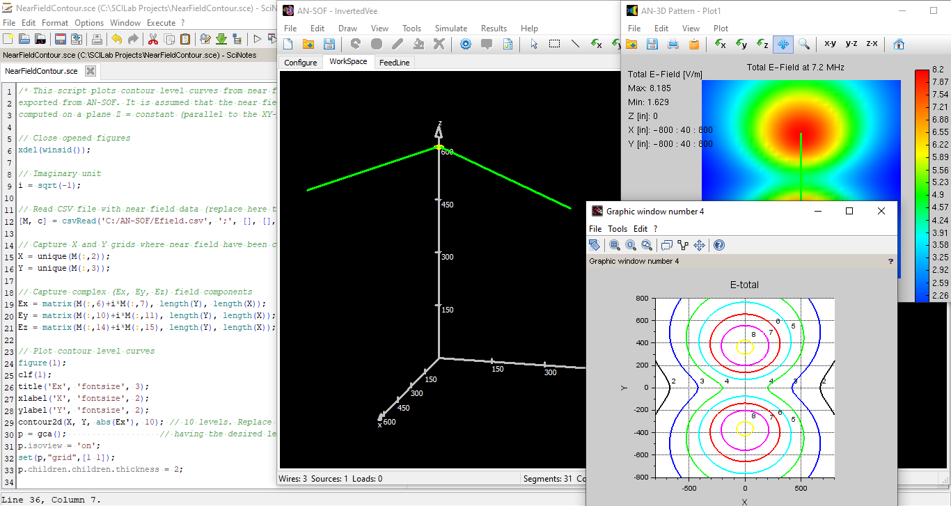
- Design Optimization: Utilize automated scripts to iterate and refine parameters for peak performance.
- R&D Efficiency: Experiment with infinite configurations in a virtual environment to reduce physical prototyping costs.
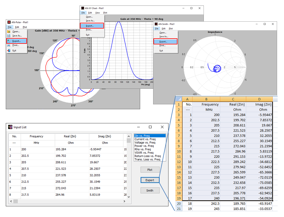
- Collaborative Reporting: Export high-resolution data and 3D visualizations to share technical findings with stakeholders.


High-Performance CAD Interface
Efficient Modeling & Visual Verification
AN-SOF eliminates the friction of traditional simulation. Our direct-edit 3D interface allows you to modify wire dimensions with a single click, bypassing the need for cumbersome spreadsheets.
- Visual Feedback: Real-time graphical viewing of sources, loads, and segmentations.
- Comprehensive Sweeps: Automatically compute electromagnetic fields, currents, and VSWR across your entire frequency range.
- Dual-View Visualization: Simultaneously analyze 2D spectral data and 3D volumetric radiation patterns for total design insight.
The Numerical Edge: CMoM vs. Traditional MoM
Beyond the “Thin-Wire” Approximation
Most traditional MoM (Method of Moments) codes rely on linear approximations and the “thin-wire” kernel, limitations that introduce significant inaccuracies in complex designs. AN-SOF utilizes the Conformal Method of Moments (CMoM) with an Exact Kernel formulation, specifically engineered to overcome the common failures of legacy simulation tools.
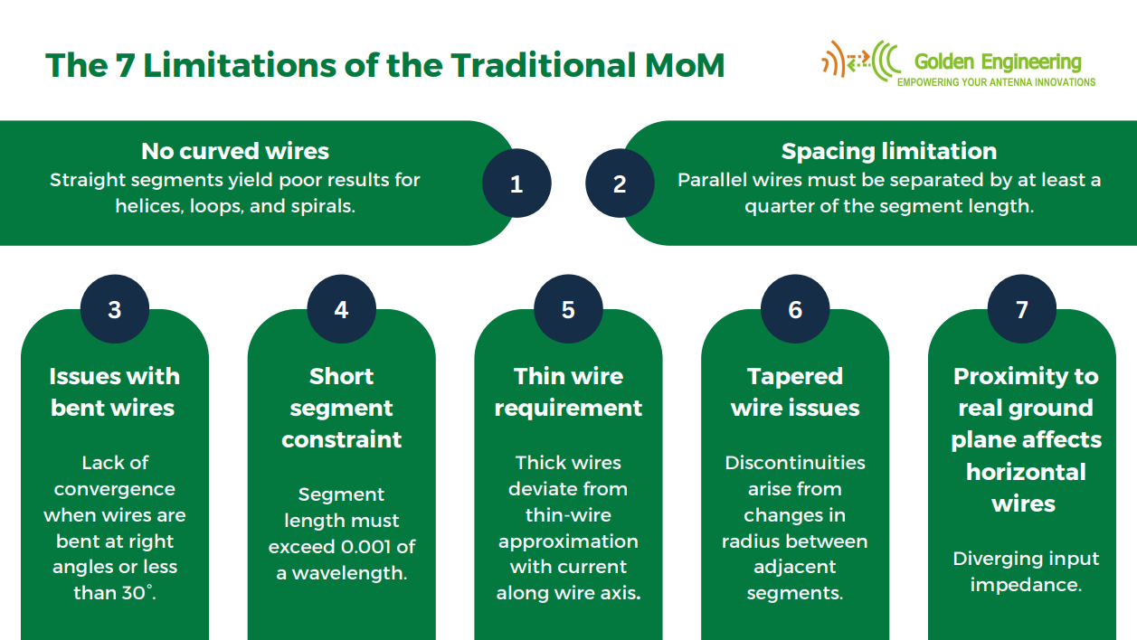
7 Critical Limitations Solved by AN-SOF:
- True Curvature: While traditional codes struggle with curved wires (helices, loops, spirals), CMoM maintains geometric fidelity for superior accuracy.
- Precision Wire Spacing: Simulate close parallel wires and transmission lines without the “quarter-segment” separation constraint.
- Angular Convergence: Eliminate inaccuracies in wire grids and right/acute bends where traditional MoM fails to converge.
- Broad-Spectrum Stability: Model from quasi-electrostatic regimes (60 Hz) to microwave frequencies without “short segment” errors.
- Surface Current Fidelity: Move beyond the thin-wire approximation; AN-SOF accounts for surface current on thick wires for real-world precision.
- Seamless Tapering: Eliminate non-physical discontinuities in designs with varying segment radii.
- Ground Plane Accuracy: Achieve stable input impedance and accurate efficiency for antennas in close proximity to lossy ground.
The Result: Faster Convergence, Absolute Precision.
By implementing a numerically exact formulation, AN-SOF reduces the computational overhead while increasing the reliability of your data.
A Unified Engineering Environment
Beyond our superior numerical engine, AN-SOF provides an integrated suite of post-processing tools to visualize and analyze your data with professional clarity.
Experience Professional Precision: Start Your Trial
Read how industry experts have validated our numerical accuracy against established electromagnetic standards. View Technical Reviews →