Search for answers or browse our Knowledge Base.
Guides | Models | Validation | Book
HF Maritime Platform Integration: Modeling a 10 MHz Naval Monopole Array
Explore the complex electromagnetic interaction between an HF monopole array and a 180-meter battleship. This AN-SOF study at 10 MHz reveals how structural resonances of a ship’s hull can cause massive impedance shifts, polarization rotation, and intricate multi-lobed radiation patterns in maritime environments.
Introduction: The Ship as a Resonant Scatterer
In the HF band (3–30 MHz), maritime antenna design faces a unique challenge: Platform Integration. Unlike higher frequencies where the vehicle body acts as a simple ground plane, at 10 MHz, the physical dimensions of a naval vessel are comparable to the wavelength ($\lambda \approx 30\text{ m}$).
A 180-meter battleship represents a $6\lambda$ structure. When antennas are placed on such a platform, they induce powerful surface currents that travel along the hull, masts, and even the artillery turrets. These induced currents create a secondary radiated field that interferes with the primary antenna radiation, resulting in the complex, multi-lobed patterns and fluctuating impedances observed in this study.
Model Geometry and Simulation Environment
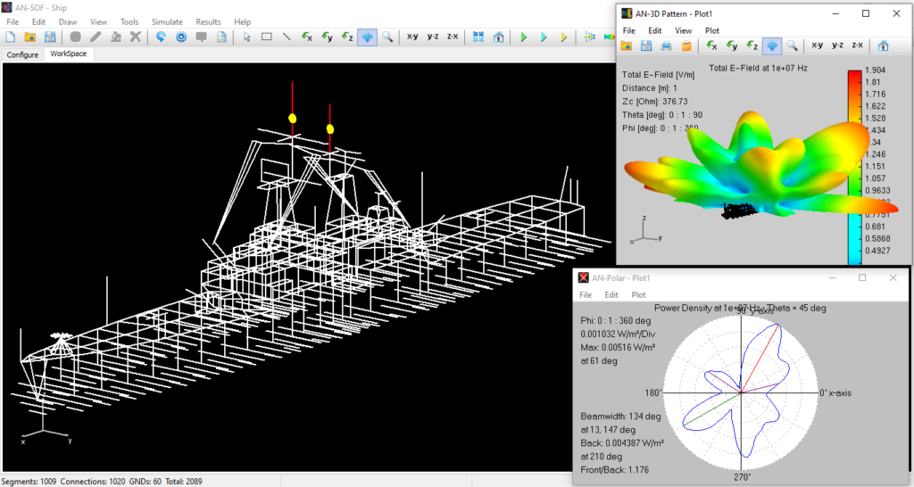
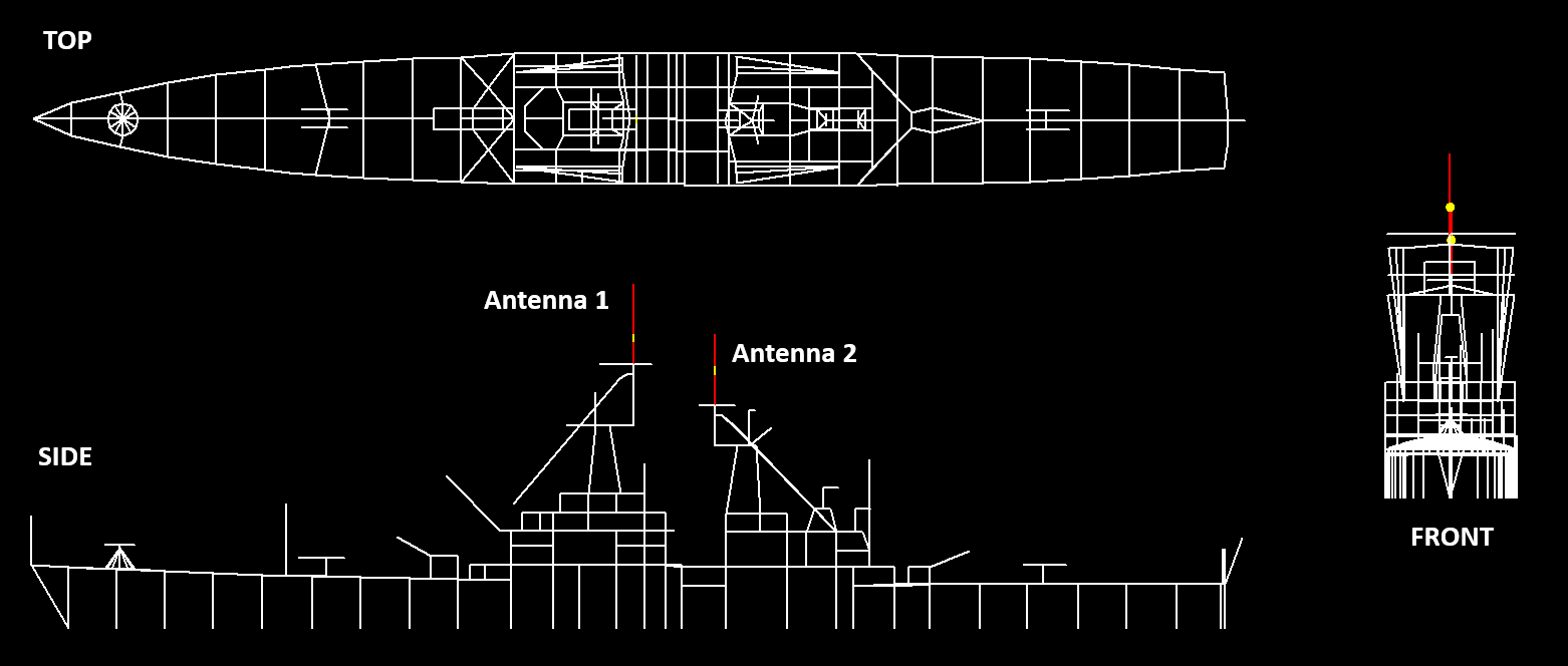
The model was created in AN-SOF as a wire grid, simulating the external metallic surface of a battleship (180m L x 20m W x 40m H) (Fig .1). To capture the complex electromagnetic environment of the high seas, the following parameters were implemented:
- Antenna Configuration: Two center-aligned monopoles (11m and 12m in length) equipped with “X” shaped wire ground radials at their bases.
- Placement: Antenna 1 is positioned forward (towards the bow), and Antenna 2 is positioned aft (towards the stern), with a 12m ($0.4\lambda$) inter-element spacing.
- Sea Surface Modeling: A Perfect Electrical Conductor (PEC) ground plane was utilized. At 10 MHz, saltwater conductivity is high enough that the PEC approximation accurately captures the “sea-reflection” phase without the computational overhead of complex Sommerfeld integrals.
- Excitation: Both antennas were fed simultaneously with a $1\text{V}$ source at $0^\circ$ phase, creating a synchronized phased-array effect.
Analysis of Input Impedance and Mutual Coupling
The simulation results across the 8–12 MHz sweep reveal a significant disparity between the two antennas:
- Antenna 1 (Bow): Remained relatively stable ($R_1: 70\text{–}120\ \Omega$; $X_1: 40\text{–}160\ \Omega$) (Fig. 2 – left). Its position near the forward artillery suggests it is less affected by the bulk of the ship’s superstructure.
- Antenna 2 (Stern): Exhibited extreme impedance volatility. The resistance ($R_2$) surged from $50\ \Omega$ to $600\ \Omega$, while the reactance ($X_2$) flipped from inductive to capacitive ($+200 \to -250\ \Omega$) right at the 10 MHz mark (Fig. 2 – right).
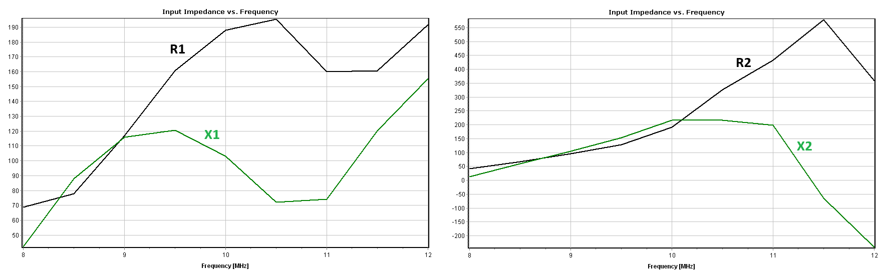
R&D Insight: This “impedance explosion” in Antenna 2 is caused by mutual coupling and structural resonance. At 10 MHz, a specific section of the ship’s superstructure (likely the central mast or cabin area) is likely becoming resonant. This structural resonance “pushes back” on Antenna 2, drastically altering its feedpoint conditions, a phenomenon often referred to as “antenna-platform detuning.”
Radiation Pattern and Polarization Dynamics
The far-field radiation pattern is remarkably intricate, exhibiting a six-lobed “fan beam” (three lobes to port, three to starboard, Fig. 3).
- Lobe Structure: The lobes are located at $0^\circ$, $30^\circ$, and $45^\circ$ elevation. This vertical “fingering” of the pattern is a classic interference effect between the direct wave and the reflected wave from the PEC “ocean” surface.
- Symmetry: The longitudinal symmetry confirms that the wire-grid ship model and antenna placements are well centered, ensuring balanced coverage on both sides of the vessel.
- Polarization Shift: Below 10 MHz, the field is primarily vertically polarized ($E_\theta$), as expected from vertical monopoles. However, above 10 MHz, horizontal polarization ($E_\phi$) increases rapidly. This is a direct consequence of the ship’s horizontal surfaces (the deck and hull) becoming large-scale radiators as they support transverse current loops at higher frequencies.
Conclusions
This AN-SOF study highlights the critical importance of platform-level modeling in naval RF design. A 10 MHz dipole that performs perfectly in free space will behave unpredictably when integrated into a 180-meter battleship.
- Platform Resonance: The ship’s hull and superstructure act as parasitic radiators, which can either enhance gain (reaching up to 12 dBi) or create deep nulls that hinder communication.
- Impedance Challenges: The massive impedance shift in the stern antenna demonstrates that “standard” matching networks are insufficient. Antenna designers must account for the ship’s own electromagnetic signature when designing the feed system.
- Polarization Control: The shift toward horizontal polarization above 10 MHz suggests that for maritime skywave communication, the ship’s structure might actually improve NVIS (Near Vertical Incidence Skywave) performance by contributing more horizontal energy at higher angles.
See Also:
Technical Keywords: Maritime HF Communication, Platform Integration, Wire-Grid Ship Modeling, Saltwater PEC Approximation, 10 MHz, Conformal MoM.
