Search for answers or browse our Knowledge Base.
Guides | Models | Validation | Book
Adding a Feed Line and Transformer
In this article, you will learn how to add a feed line and transformer to your AN-SOF project. These components are essential for connecting your antenna structure to the external circuitry and impedance matching.
In the case of a transmitting antenna with a single feed port, the feeder used to connect the transmitter to the antenna terminals can be modeled in the Feeder tab, as shown in Fig. 1. The feeder consists of a transmission line, or feed line, and an impedance transformer.
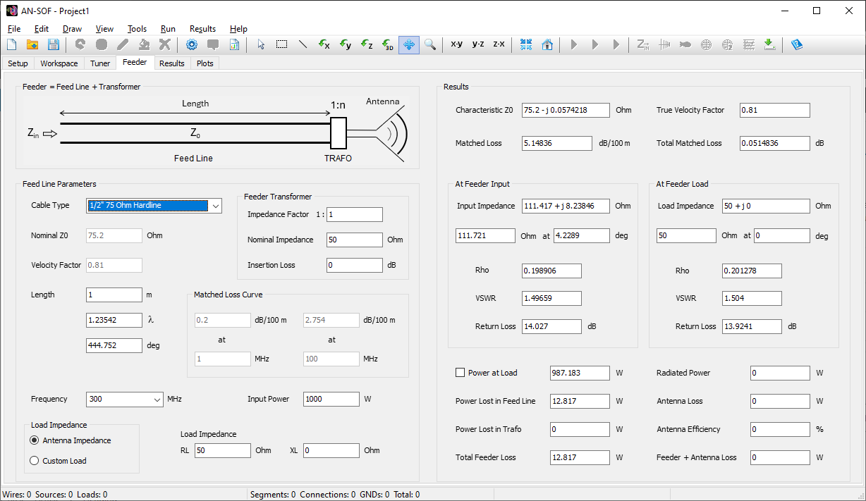
Setting the Impedance Transformer
The transformer, also known as trafo, can represent a balun or unun that connects directly to the antenna terminals to divide its input impedance by a factor, n. In the Feeder Transformer box, three parameters can be specified:
Impedance Factor 1:n
Here, “n” is the factor by which the antenna input impedance will be divided. For example, if we have a folded half-wave dipole, which typically has an input impedance on the order of 300 Ohms, we can set n = 4 to get 300/4 = 75 Ohms of input impedance after the transformer (i.e., a 1:4 balun). If the input impedance is complex, both its real and imaginary parts will be divided by n.
If the transformation factor is in the range 0 < n < 1, the transformer input impedance will be greater than the antenna impedance. By setting n = 1, we can represent a 1:1 transformer, also known as a common-mode choke or line isolator, used to transform a balanced or symmetrical antenna to an unbalanced feed line.
Note that “n” is the impedance transformer factor, not the voltage transformation factor. In a transformer, which is composed of a primary winding (inductor or coil) and a secondary winding, the voltage transformation factor is n-1/2.
Nominal Impedance
All actual impedance transformers, whether baluns or ununs, are fabricated for a nominal impedance, for which the manufacturer warranties the transformer performance in terms of bandwidth and insertion loss. So, if a lossy transformer is going to be modeled, we should set its nominal impedance according to the manufacturer’s datasheet.
Insertion Loss
The insertion loss of the transformer can be set in decibels to represent the actual loss given in its datasheet. The insertion loss is defined as the power lost, in decibels, inside the transformer, so that its output power will be lower than its input power due to losses in the transformer materials (coil resistivity, magnetic core losses, etc.).
Note: If no transformer is needed, just set n = 1 and an insertion loss of 0 dB.
Setting Feed Line Parameters
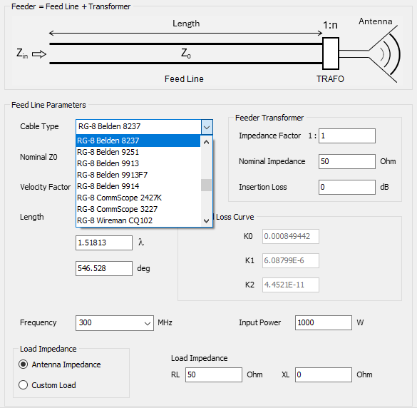
In AN-SOF, various real-life transmission line types are available, each with matched loss parameters adjusted according to the cable datasheets. These cable types are organized by part numbers and include the manufacturer’s name.
For example, entering “RG-8” in the Cable Type option will display this part number for different manufacturers, as shown in Fig. 2. Selecting RG-8 Belden 8237 will reveal a set of K0, K1, and K2 parameters. These constants have been adjusted to match the loss curve as a function of frequency, based on the matched loss vs. frequency table published in the cable datasheet. K0 relates to the DC losses in the transmission line conductors, K1 to the skin effect losses dependent on the square root of frequency, and K2 to dielectric losses increasing linearly with frequency. These losses are then considered in the standard RLGC model of a lossy transmission line.
The nominal values of the cable characteristic impedance Z0 and velocity factor will also be shown for the chosen part number and manufacturer. After selecting the cable type, you can set the operating frequency and input power to the feed line. The frequency can be chosen from a list that displays the frequencies set in the Setup tab.
Next, you can set the length of the cable, entered according to the length unit used for drawing wires in the workspace. To change the length unit, go to Tools > Preferences in the main menu. As you type the cable length, the length measured in wavelengths (λ) and electrical degrees will be automatically displayed. In fact, all feed line results are calculated automatically by modifying any of the feed line parameters.
You can then choose the load impedance of the feed line. The default option considers the Antenna Impedance as the load impedance of the transmission line, automatically displaying the antenna input impedance at the chosen frequency as the load for the line. However, you can enter any value for the line load impedance by selecting the Custom Load option. This allows you to use the Feed Line tabsheet as an independent calculator for transmission lines.