Search for answers or browse our Knowledge Base.
Guides | Models | Validation | Book
Connecting Transmission Lines
Any transmission lines added through the Transmission Lines command (Ctrl + L) under the Draw menu will remain in the table until the user decides to remove or modify them. During calculations, only transmission lines with both ports connected to respective wire segments will be considered for simulation. Any lines with a single port connected or both ports disconnected will be omitted in the calculations.
To connect a transmission line between two wire segments, follow these steps:
- Right-click on the first wire to select it and choose the Source / Load / TL (Ctrl + Ins) command from the pop-up menu. This will open a horizontal toolbar with a slider control, Fig. 1.
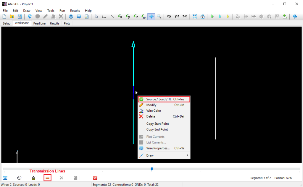
- Use the slider to select the specific segment of the first wire to which you want to connect a port of the transmission line.
- Once you’ve chosen the segment, click on the Transmission Lines button on the horizontal toolbar to open the Transmission Lines table, Fig. 2.
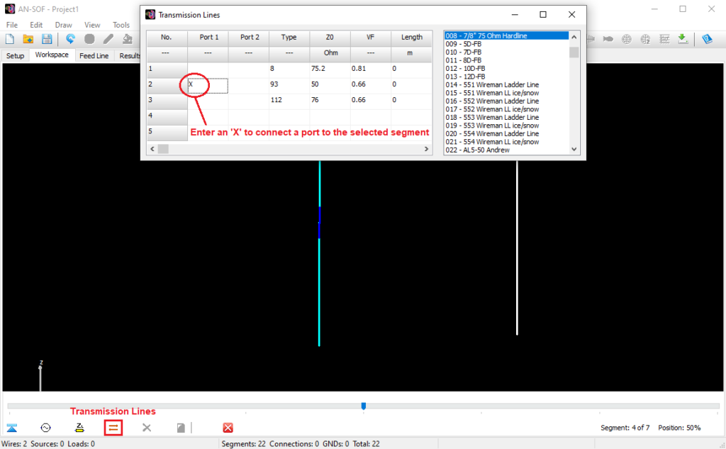
- Enter an “x” or “X” (without quotes) in the corresponding cell for the port you want to connect to the selected segment (the cells located below the “Port 1” and “Port 2” columns), Fig. 2. You can enter an “X” for all the ports that need to be connected to the same segment as multiple transmission lines can be connected to it. Finally, close the Transmission Lines window.
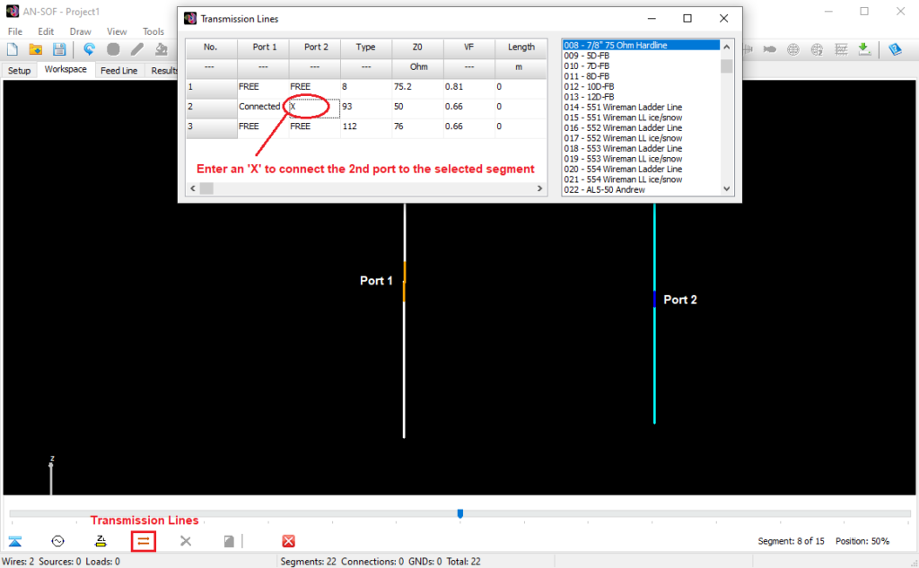
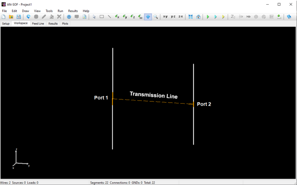
- Select the second wire and repeat steps 1-4 to connect the second port of the transmission line to another segment, Fig. 3. The transmission lines with both ports connected will be graphically displayed as shown in Fig. 4.
While performing this procedure, you have the option to add more transmission lines directly in the “Transmission Lines” dialog window. This saves you from having to follow the steps outlined in Adding Transmission Lines. The advantage of adding transmission lines here is that you can edit the connections of the lines in the “Port 1” and “Port 2” columns. However, with the Draw > Transmission Lines (Ctrl + L) command, you can quickly edit the lines (Z0, VF, length, etc.) if you don’t need to change the port connections.
A port that is already connected to a segment will show the status as “Connected,” while if it is not connected to any segment, it will display the status as “FREE”. When we are on a selected segment, a connected port will show the status as “Here,” which refers to the port being connected specifically to that selected segment.
To disconnect a port from a segment, enter the word “FREE” (without quotes, in uppercase) in the corresponding cell instead of an “X”. This allows you to use the “X” and “FREE” commands to easily connect and disconnect ports on a selected segment.
The transmission lines that have both ports connected to segments are displayed as straight dashed lines in orange color in the workspace, Fig. 4. An arrow will indicate the direction of the line, which goes from port 1 to 2. Since the length of a line is another parameter that is entered, such as its characteristic impedance and velocity factor, the length of the line in the workspace may not represent the configured or “real” length of the line.
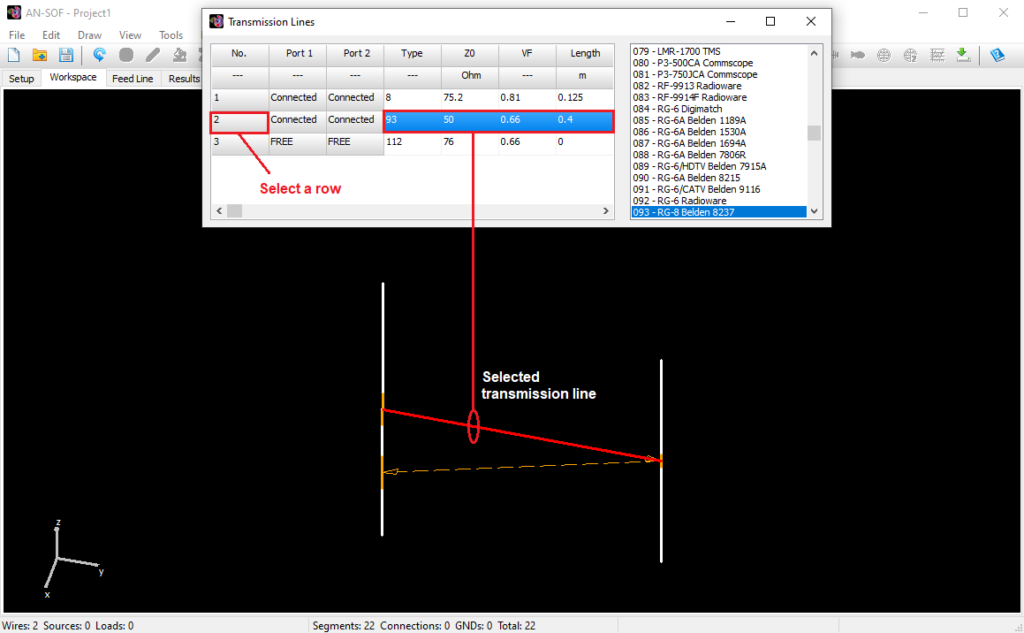
If you select a row by clicking on the row number in the Transmission Lines table, the corresponding line will be highlighted in red in the workspace (if it has both ports connected to segments), Fig. 5. This way, you can visually identify which line you are editing.
IMPORTANT Information
- A transmission line with only one port connected to a wire segment will not be considered in the calculations. Instead, it exists as a row within the table, which can be used as a library of lines to select from and connect to the wire structure. Therefore, when a port is FREE, it does not mean that the corresponding end of the transmission line is open circuited, but rather that this line will simply be omitted in the simulation. It is sufficient for only one port to be FREE for the line to be omitted. If you need to connect a line with an open or short-circuited end, please refer to Open and Short-Circuited Lines for detailed instructions.
- A voltage or current source can be connected to any segment where one or more transmission line ports are connected. In this case, the sources will always be “ideal”, i.e., with zero/infinite internal impedance (zero for voltage sources and infinite for current sources), unlike in an ordinary segment without a port connected, where sources may have non-zero/finite internal impedance (in AN-SOF, current sources should always have a finite internal impedance because this impedance is connected in parallel with the current source).
- In each segment, only transmission line ports or a load impedance are allowed, but not both. If a port is connected to a segment where a load impedance already exists, this impedance will be eliminated, and vice versa. If you need to connect a load impedance in series with the port of a transmission line, connect the impedance in an adjacent segment to the port.
- When there are transmission lines in the model, the NGF (Numerical Green’s Function) option will be automatically enabled in the Settings panel of the Setup tabsheet. This way, calculations will be performed faster in the next simulation if only the parameters of the transmission lines are modified while the wire structure remains unchanged.
- It is recommended to connect transmission lines after drawing and segmenting the wire structure. If the number of segments changes, the lines may become disconnected and need to be manually reconnected using the procedure described in this section.
- To ensure a smooth calculation process, AN-SOF will verify the correct connections between the transmission lines and the wire segments. If AN-SOF detects any errors, it will promptly remove the faulty connection by setting the corresponding port to FREE state.