Search for answers or browse our Knowledge Base.
Guides | Models | Validation | Blog
A Closer Look at the HF Skeleton Slot Antenna
In this post, we’re going to dive into the world of HF Skeleton Slot Antennas, a unique array of two tightly coupled loops with a bi-directional pattern.
What is a Skeleton Slot Antenna?
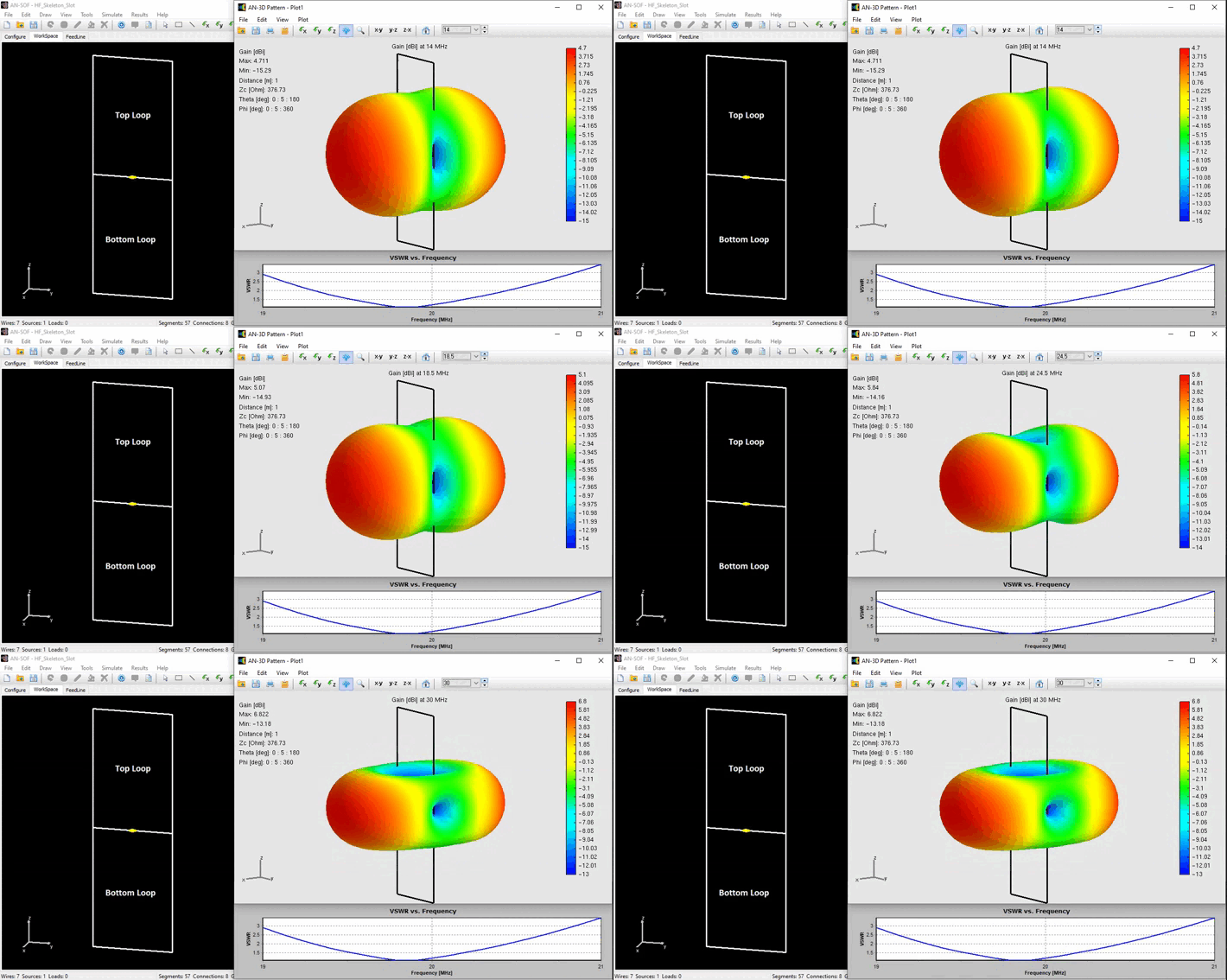
The Skeleton Slot Antenna, believed to originate in the UK post-World War II for TV use, derives its name from the slot antenna. This aperture antenna forms by cutting a rectangular hole in a conducting sheet, effectively acting as a “photographic negative” of a dipole, with the slot serving as the radiating element. Simplifying the design to its bare essentials yields the skeleton slot. For analytical purposes, we can visualize this antenna as two closely interconnected loops sharing a single feed point. The antenna, including its top and bottom loops, as well as simulation results, is shown in the figure below.

This antenna design is known for its bi-directional radiation pattern and is well-suited for high-frequency (HF) bands, specifically within the 14 to 28 MHz range, when appropriately impedance matched. We can observe how the radiation pattern changes within this frequency range, with the gain varying from 4.7 to 6.8 dBi, while the antenna continues to maintain its bidirectionality.
The Key to Self-Resonance
One of the standout features of the Skeleton Slot Antenna is its self-resonant capability. This occurs when the perimeter of each loop is approximately equal to one wavelength at the desired operating frequency, and the ratio between the length and width of each rectangular loop is 3:2. In the example depicted in the figure above, each loop measures 4.5 x 3 meters, resulting in a resonant frequency of 19.8 MHz, as indicated by the dip in the VSWR curve.
Note that the perimeter of each loop is 2 x (4.5 + 3) = 15 meters, which is precisely the wavelength at 20 MHz, very close to the resonant frequency of 19.8 MHz.
In the January 1955 issue of The Shortwave Magazine, there is an article by B. Sykes (G2HCG) titled “The Skeleton Slot Aerial System” (Vol. XII, No. 11, pp. 594-598). In this article, the antenna is described as an array of two dipoles. The author, through experimental findings, concludes that the optimal length of the sides of the entire antenna should be 0.56 times the wavelength (λ), with a total length-to-width ratio of 3:1. These values, applied to each individual loop, result in a perimeter of 2 x (1/2 + 1/3) x 0.56λ = 0.93λ.
However, it’s worth noting that the radiation pattern and input impedance behavior of the antenna correspond more closely to that of a loop-type antenna, composed of two tightly coupled loops in this case. In this configuration, the antenna resonates when its perimeter measures approximately one wavelength. To illustrate this point, you can refer to the article “Input Impedance and Directivity of Large Circular Loops,” which validates AN-SOF results against theory.
Benefits of the HF Skeleton Slot Antenna
- Bi-Directional Pattern: This antenna’s bi-directional pattern makes it a valuable choice for situations where we need to communicate in two opposite directions simultaneously.
- Frequency Range: The HF Skeleton Slot Antenna covers a broad frequency range within the HF spectrum, making it versatile for various amateur radio and communication applications.
- Self-Resonance: Achieving self-resonance simplifies the tuning process and ensures optimal performance at the desired frequency.
In conclusion, the Skeleton Slot Antenna is a remarkable choice for HF communication enthusiasts. Its bi-directional pattern, wide frequency range, and self-resonant capabilities make it a valuable addition to your radio setup.
See Also:
Design Guidelines for Skeleton Slot Antennas: A Simulation-Driven Approach
