How Can We Help?
Search for answers or browse our Knowledge Base.
Guides | Models | Validation | Blog
-
Guides
-
-
- Evaluating EMF Compliance - Part 2: Using Near-Field Calculations to Determine Exclusion Zones
- Beyond Analytical Formulas: Accurate Coil Inductance Calculation with AN-SOF
- Complete Workflow: Modeling, Feeding, and Tuning a 20m Band Dipole Antenna
- DIY Helix High Gain Directional Antenna: From Simulation to 3D Printing
- Evaluating EMF Compliance - Part 1: A Guide to Far-Field RF Exposure Assessments
- Design Guidelines for Skeleton Slot Antennas: A Simulation-Driven Approach
- Simplified Modeling for Microstrip Antennas on Ungrounded Dielectric Substrates: Accuracy Meets Simplicity
- Fast Modeling of a Monopole Supported by a Broadcast Tower
- Linking Log-Periodic Antenna Elements Using Transmission Lines
- Wave Matching Coefficient: Defining the Practical Near-Far Field Boundary
- AN-SOF Mastery: Adding Elevated Radials Quickly
- Enhancing Antenna Design: Project Merging in AN-SOF
- On the Modeling of Radio Masts
- The Equivalent Circuit of a Balun
- AN-SOF Antenna Simulation Best Practices: Checking and Correcting Model Errors
-
-
- AN-SOF 9.50 Release: Streamlining Polarization, Geometry, and EMF Calculations
- AN-SOF 9: Taking Antenna Design Further with New Feeder and Tuner Calculators
- AN-SOF Antenna Simulation Software - Version 8.90 Release Notes
- AN-SOF 8.70: Enhancing Your Antenna Design Journey
- Introducing AN-SOF 8.50: Enhanced Antenna Design & Simulation Software
- Get Ready for the Next Level of Antenna Design: AN-SOF 8.50 is Coming Soon!
- Explore the Cutting-Edge World of AN-SOF Antenna Simulation Software!
- Upgrade to AN-SOF 8.20 - Unleash Your Potential
- AN-SOF 8: Elevating Antenna Simulation to the Next Level
- New Release: AN-SOF 7.90
- AN-SOF 7.80 is ready!
- New AN-SOF User Guide
- New Release: AN-SOF 7.50
- AN-SOF 7.20 is ready!
- New Release :: AN-SOF 7.10 ::
- AN-SOF 7.0 is Here!
- New Release :: AN-SOF 6.40 ::
- New Release :: AN-SOF 6.20 ::
- Show All Articles (3) Collapse Articles
-
-
-
-
Models
-
- Download Examples
- Modeling a Center-Fed Cylindrical Antenna with AN-SOF
- Yagi-Uda Array
- Monopole Over Real Ground
- Helix Antenna in Axial Mode
- Modeling a Circular Loop Antenna in AN-SOF: A Step-by-Step Guide
- A Transmission Line
- An RLC Circuit
- Explore 5 Antenna Models with Less Than 50 Segments in AN-SOF Trial Version
-
- Modeling a Super J-Pole: A Look Inside a 5-Element Collinear Antenna
- Simulating the Ingenious Multiband Omnidirectional Dipole Antenna Design
- The Loop on Ground (LoG): A Compact Receiving Antenna with Directional Capabilities
- Precision Simulations with AN-SOF for Magnetic Loop Antennas
- Advantages of AN-SOF for Simulating 433 MHz Spring Helical Antennas for ISM & LoRa Applications
- Radio Mast Above Wire Screen
- Square Loop Antenna
- Receiving Loop Antenna
- Monopole Above Earth Ground
- Top-Loaded Short Monopole
- Half-Wave Dipole
- Folded Dipole
- Dipole Antenna
- The 5-in-1 J-Pole Antenna Solution for Multiband Communications
-
- The Lazy-H Antenna: A 10-Meter Band Design Guide
- Extended Double Zepp (EDZ): A Phased Array Solution for Directional Antenna Applications
- Transmission Line Feeding for Antennas: The Four-Square Array
- Log-Periodic Christmas Tree
- Enhancing VHF Performance: The Dual Reflector Moxon Antenna for 145 MHz
- Building a Compact High-Performance UHF Array with AN-SOF: A 4-Element Biquad Design
- Building a Beam: Modeling a 5-Element 2m Band Quad Array
- Broadside Dipole Array
- Log-Periodic Dipole Array
- Broadband Directional Antenna
- A Closer Look at the HF Skeleton Slot Antenna
- The 17m Band 2-Element Delta Loop Beam: A Compact, High-Gain Antenna for DX Enthusiasts
- Enhancing Satellite Links: The Moxon-Yagi Dual Band VHF/UHF Antenna
-
-
Validation
-
-
- Simple Dual Band Vertical Dipole for the 2m and 70cm Bands
- Linear Antenna Theory: Historical Approximations and Numerical Validation
- Validating Panel RBS Antenna with Dipole Radiators against IEC 62232
- Directivity of V Antennas
- Enhanced Methodology for Monopoles Above Radial Wire Ground Screens
- Dipole Gain and Radiation Resistance
- Convergence of the Dipole Input Impedance
- Validating Dipole Antenna Simulations: A Comparative Study with King-Middleton
-
Print
Incident Field Parameters
Created OnOctober 13, 2022
Updated OnApril 30, 2023
By:Tony Golden
The following incident field parameters can be set in the Excitation panel > of the Setup tabsheet after clicking on the Incident Field option:
- E-Field Major Axis: Amplitude, in V/m (Volts rms per meter), of the linearly polarized incoming electric field. For elliptical polarization, it is the length of the major ellipse axis.
- Axial Ratio: For an elliptically polarized plane wave, it is the ratio of the minor axis to the major axis of the ellipse. A positive (negative) axial ratio defines a right-handed (left-handed) ellipse. If the axial ratio is set to zero, a linearly polarized plane wave is defined.
- Phase Reference: Phase, in degrees, of the incident plane wave at the origin of coordinates. It can be used to change the phase reference in the calculation. Its value only shifts all phases in the structure by the given amount.
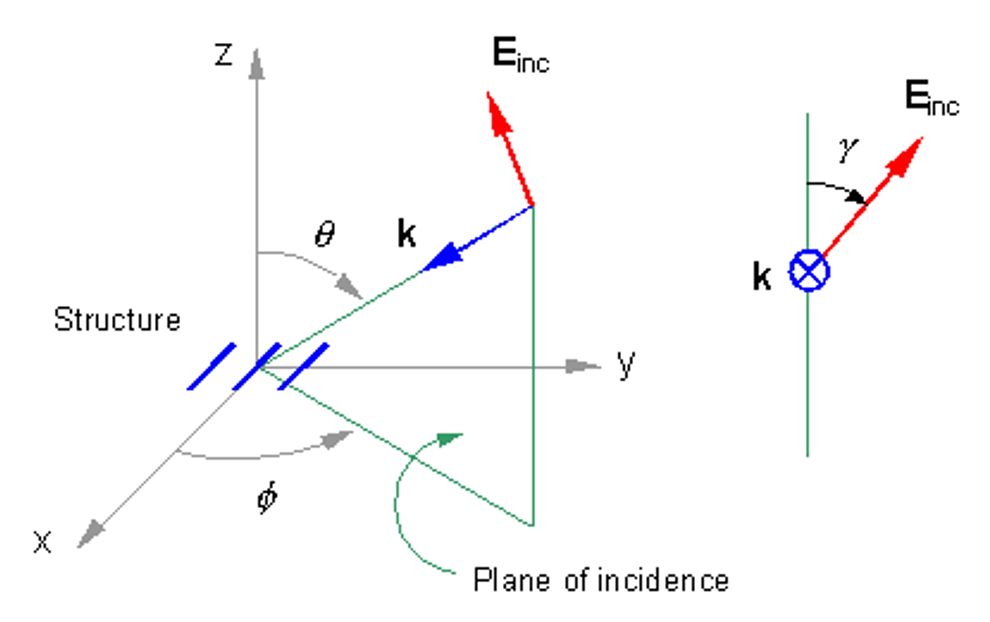
- Gamma: Polarization angle of the incident electric field in degrees. For a linearly polarized wave, Gamma is measured from the plane of incidence to the direction of the electric field vector, Fig. 1. For an elliptically polarized wave, Gamma is the angle between the plane of incidence and the major ellipse axis.
- Theta: Zenith angle of the incident direction in degrees, Fig. 1.
- Phi: Azimuth angle of the incident direction in degrees, Fig. 1.

Note
When an incident plane wave is used as excitation, all discrete sources, if any, will not be considered in the simulation.
Table of Contents
