Search for answers or browse our Knowledge Base.
Guides | Models | Validation | Book
Validating AN-SOF Simulations for Gain and VSWR of Helix Antennas in Axial Mode
AN-SOF simulations of axial-mode helical antennas closely match John D. Kraus’s classic measurements for gain and VSWR, confirming its accuracy. Using the Conformal Method of Moments, AN-SOF models true helix curvature, delivering reliable predictions for high-gain circularly polarized designs.
Helical antennas in axial mode are widely used when a high-gain, circularly polarized radiation pattern is required. Applications range from satellite communications to deep-space telemetry. Their performance, however, is sensitive to geometric parameters such as circumference, pitch angle, and number of turns. In this article, we compare AN-SOF simulation results for gain and voltage standing wave ratio (VSWR) with experimental data reported by John D. Kraus in his classic reference Antennas (2nd Edition, McGraw-Hill, 1988).
Our goal is to show that AN-SOF’s Conformal Method of Moments, which models curved wires with true curvature rather than approximating them as a chain of straight segments, can closely reproduce the measured behavior of helical antennas operating in axial mode.
Modeling the Helix in AN-SOF
In AN-SOF, a helical antenna can be created directly using the Helix command, which allows input in terms of pitch (distance between turns) or pitch angle (in degrees). This makes it straightforward to replicate configurations described in the literature. For readers new to this process, we have a dedicated guide:
Gain vs. Circumference-to-Wavelength Ratio
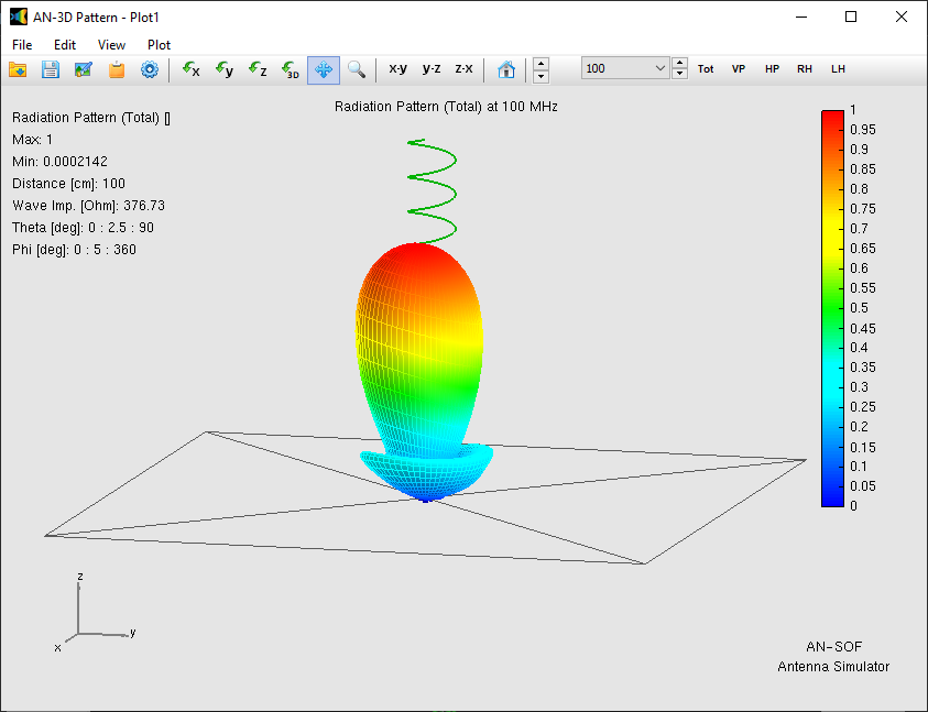
A helix in axial mode produces a main lobe along its axis and several smaller sidelobes (Fig. 1). Kraus’s measurements showed that, for a fixed pitch angle, the gain increases with the normalized circumference $C/\lambda$ up to a point, then levels off or decreases.
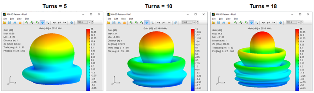
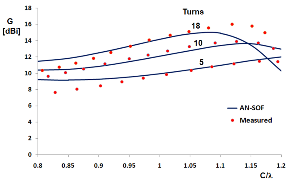
In his experiments, Kraus plotted gain as a function of $C/\lambda$ for several numbers of turns at a pitch angle of $\alpha = 12.8^\circ$. To compare with these results (Fig. 2), we modeled antennas with matching parameters in AN-SOF.
Since the original publication did not specify details such as wire radius or the dimensions of the short feed connection to the ground plane, these parameters were adjusted within reasonable ranges to achieve a consistent match across all curves. The simulated gain curves aligned well with Kraus’s data, reproducing the characteristic maxima around $C/\lambda \approx 1.1–1.2$ for multiple turn counts.
VSWR Behavior
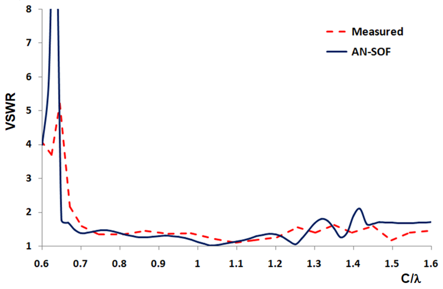
Kraus also presented feedpoint measurements for a 6-turn, $\alpha = 14^\circ$ helical antenna, publishing the results in terms of VSWR rather than complex impedance. Figure 3 reproduces these data alongside the AN-SOF simulation results.
The comparison shows excellent agreement: the simulation captures both the VSWR dip near $C/\lambda = 0.65$ and the multiple peaks between $C/\lambda = 1.2$ and $1.5$. This level of correspondence between measurement and simulation reinforces the reliability of AN-SOF’s numerical engine.
Why the Conformal Method of Moments Matters
Traditional Method of Moments (MoM) implementations approximate curved wires as a sequence of short straight segments, which can introduce geometric errors in tightly wound antennas. AN-SOF’s Conformal MoM instead uses segments that exactly follow the curvature of the helix. This eliminates the need for excessive segmentation to achieve accuracy, resulting in both improved fidelity and reduced computational overhead.
Conclusion
The comparisons presented here confirm that AN-SOF can accurately predict both gain and VSWR trends for axial-mode helical antennas, closely matching the benchmark measurements of Kraus. This capability makes AN-SOF a valuable tool for engineers and hobbyists designing high-performance circularly polarized antennas.
By combining precise geometry modeling with robust electromagnetic algorithms, AN-SOF bridges the gap between theoretical design and real-world performance, a must-have advantage for serious antenna simulation work.
See Also:
Technical Keywords: Axial-Mode Helix, John D. Kraus, Antenna Gain, VSWR, Conformal Method of Moments (CMoM), Circular Polarization, Numerical Validation, Helix Curvature, Satellite Communications, Antenna Simulation.
