Search for answers or browse our Knowledge Base.
Guides | Models | Validation | Book
Feeder Results: Input Impedance and Losses
After specifying the feeder parameters in the left side of the Feeder tab, the following results will be obtained in its right side (Fig. 1):
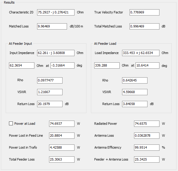
Characteristic Z0
This is the “true” characteristic impedance of the feed line obtained from the RLGC model via the K0, K1, and K2 constants. The real part of Z0 may differ somewhat from the nominal Z0 depending on frequency and losses in the transmission line. An imaginary part will always appear in Z0 due to non-zero losses. So, note that the true characteristic Z0 will generally differ from the “Nominal Z0” (Z0 in the cable datasheet).
True Velocity Factor
This is the “true” velocity factor obtained from the RLGC model of the transmission line, where the wavenumber (and wavelength inside the line) is affected by losses. The velocity factor will be modified relative to its nominal value accordingly. Therefore, the true velocity factor is a function of frequency and losses in the line.
Matched Loss
Any cable datasheet contains a table of matched loss values expressed in dB/100 feet or dB/100 m as a function of frequency. These values correspond to the attenuation of the line when it is matched (the line has a load impedance equal to Z0). So, the Matched Loss value shown in the Results panel is the attenuation of the line corresponding to the selected frequency.
Total Matched Loss
This is the matched loss that would be obtained for the specified length of the cable. Therefore, the Total Matched Loss equals the Matched Loss (dB/100 feet or dB/100 m) multiplied by the cable length.
At Feeder Input
The input impedance of the feeder (feed line + transformer) will be shown as well as the reflection coefficient (Rho), VSWR, and return loss, all referred to the true characteristic impedance of the feed line. This is the impedance at the feed line end opposite to the end where the load or antenna is connected.
At Feeder Load
The load impedance connected to the feeder (feed line + transformer) will be shown as well as the reflection coefficient (Rho), VSWR, and return loss, all referred to the true characteristic impedance of the feed line. The load impedance will be the antenna input impedance if the Antenna Impedance option was selected as a parameter for the feed line in the left side of the Feeder tab. If a “Custom Load” was selected, then the load impedance will be that entered by the user.
Power at Load
This is the power in Watts consumed at the feeder load impedance or effectively delivered to the antenna terminals. This power will be less than the input power specified as an input parameter for the feed line if the transmission line has losses. The power at the load will be equal to the input power in the case of a lossless transmission line. Check the Power at Load option to automatically set this power as the input power delivered to the antenna terminals. Otherwise, the antenna input power will be that set manually in the Excitation panel of the Setup tab.
Power Lost in Feed Line
This is the power lost along the transmission line in Watts.
Power Lost in Trafo
This is the power lost in the feeder transformer in Watts.
Total Feeder Loss
This is the sum of the powers lost in the feed line and in the transformer.
Radiated Power
This is the power in Watts radiated by the antenna when it is fed using the Power at Load, which is the power effectively delivered to the load impedance of the feeder. The radiated power will be different from the power delivered by the feeder if the antenna itself has its own losses. The radiated power will be shown if the option Antenna Impedance was selected as a load impedance for the feeder in the left side of the Feeder tab.
Antenna Loss
This is the power lost in the antenna structure. It will be shown if the option Antenna Impedance was selected as a load impedance for the feeder in the left side of the Feeder tab.
Antenna Efficiency
This is the ratio of the antenna radiated power to the antenna input power (the power delivered by the feeder). It is expressed as a percentage as it is usual. It will be shown if the option Antenna Impedance was selected as a load impedance for the feeder in the left side of the Feeder tab.
Feeder + Antenna Loss
This is the sum of the powers lost in the feeder (feed line + transformer) and antenna.