Search for answers or browse our Knowledge Base.
Guides | Models | Validation | Book
Input Impedance and Directivity of Large Circular Loops: Theory vs. Numerical Simulation
Moving beyond the uniform-current simplifications of small antennas, this article analyzes the electromagnetic behavior of electrically large circular loops. By benchmarking AN-SOF numerical results against classical Fourier theory, we explore how loop circumference and wire thickness influence non-uniform current distributions, parallel/series resonances, and axial directivity. This detailed study validates the accuracy of CMoM for curved radiators.
The Transition from Small to Large Loop Theory
In the study of antenna electromagnetics, circular loops are often classified by their electrical size. For “small” loops, where the circumference $C$ is a tiny fraction of the wavelength $\lambda$, the current distribution is assumed to be uniform. This simplification allows for straightforward closed-form expressions for radiation resistance and directivity. However, as the loop circumference becomes comparable to or exceeds the wavelength, this assumption is no longer physically valid.
For electrically large loops, the current distribution becomes non-uniform and is typically approximated in analytical theory using a Fourier series expansion. This non-uniformity dictates a fundamental shift in the antenna’s impedance and radiation characteristics. Furthermore, theoretical models often employ a “delta-gap” voltage source for excitation. While useful, this approach can lead to convergence issues regarding input impedance, challenges that are effectively addressed by the high-fidelity exact kernel implementations found in modern full-wave solvers like AN-SOF.
Geometric Definitions and the Thickness Parameter
To characterize the performance of a large loop, two primary variables are used: the normalized circumference ($C/\lambda$) and the wire thickness. The thickness is described by Hallen’s expansion parameter, $\Omega$, which relates the loop’s circumference $C = 2\pi r$ to the conductor’s radius $a$:
$\displaystyle \Omega \,=\, 2 \, \ln \left( \frac{2\pi r}{a} \right)$
where $r$ is the loop’s radius.
This parameter is crucial because the resonance points and peak impedance values of the loop are highly sensitive to the diameter of the wire. A lower $\Omega$ value indicates a thicker conductor, which typically results in a broader bandwidth and a shift in the resonant frequencies.
Evolution of the Radiation Pattern
The “donut-shaped” omnidirectional pattern characteristic of small loops disappears as the electrical size increases. For a loop with a circumference of one wavelength ($C/\lambda = 1$), the radiation pattern undergoes a dramatic transformation (Fig. 1). Instead of a null along the axis of the loop, the pattern exhibits two primary maxima directed along the axis. Simultaneously, two nulls appear in the plane of the loop, positioned perpendicular to the feed point.
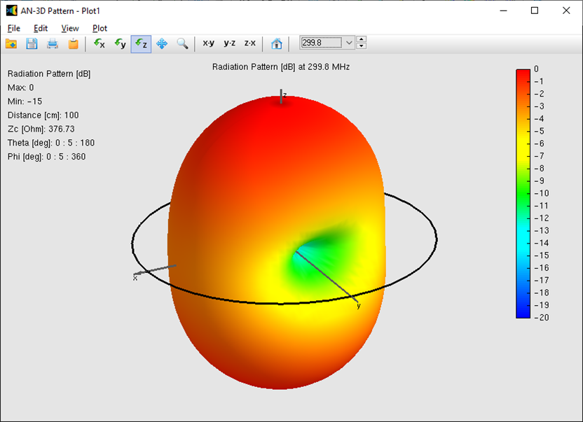
This directional shift is a direct result of the phase changes in the current as it travels around the larger perimeter. Because the current is no longer in phase at all points, the far-field contributions interfere constructively along the axis, creating a more concentrated beam compared to smaller radiators.
Directivity Benchmarking: AN-SOF vs. Fourier Theory
The precision of the Conformal Method of Moments (CMoM) in AN-SOF is demonstrated by comparing its directivity results against established theoretical benchmarks. The following data compares peak directivity (in dBi) for loops of varying thickness ($\Omega$) and electrical size ($C/\lambda$):
| $\Omega$ | $C/\lambda$ | $D \text{ [dBi]}$ Theory | $D \text{ [dBi]}$ AN-SOF | Error % |
| 8 | 1 | 3.344 | 3.36 | 0.478 |
| 10 | 1 | 3.412 | 3.411 | -0.0293 |
| 12 | 1 | 3.442 | 3.439 | -0.0872 |
| 20 | 1 | 3.476 | 3.473 | -0.0863 |
| $\Omega$ | $C/\lambda$ | $D \text{ [dBi]}$ Theory | $D \text{ [dBi]}$ AN-SOF | Error % |
| 8 | 1.48 | 4.626 | 4.684 | 1.25 |
| 10 | 1.45 | 4.592 | 4.615 | 0.501 |
| 12 | 1.43 | 4.523 | 4.54 | 0.376 |
| 20 | 1.39 | 4.354 | 4.368 | 0.322 |
The high degree of correlation (errors generally below 0.5%) validates the software’s ability to model curved structures accurately. Notably, where slight discrepancies exist ($\Omega = 8$ and $C/\lambda = 1.48$), they arise because the AN-SOF exact kernel provides a more realistic representation of thick-wire physics than the idealized thin-wire approximations used in classical Fourier theory.
Analysis of Input Impedance and Resonance
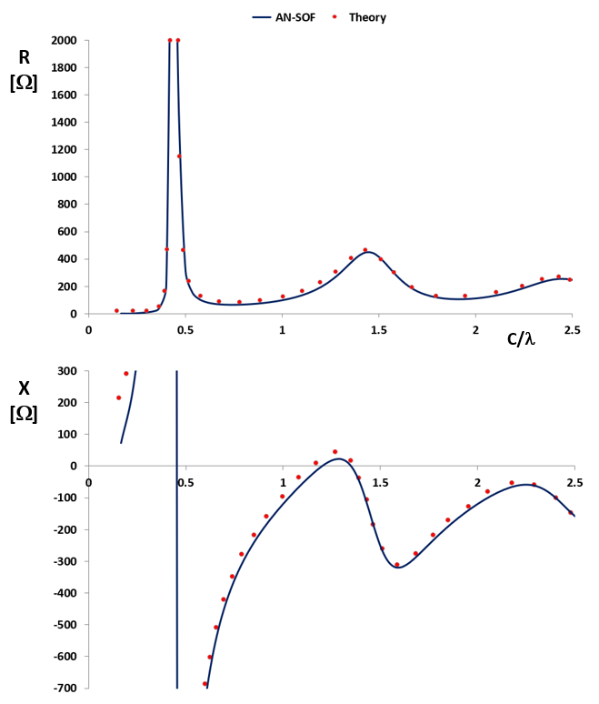
The input impedance of a circular loop is highly frequency-dependent, as shown in Fig. 2 for $\Omega = 10$. By varying the normalized circumference $C/\lambda$, we can identify several distinct regions of operation:
- Small Loop/Inductive Region ($C/\lambda < 0.25$): The impedance is characterized by very low radiation resistance and high inductive reactance.
- Parallel Resonance ($C/\lambda \lesssim 0.5$): As the loop approaches a half-wavelength in circumference, it enters a parallel resonance. This is marked by a sharp “jump” in reactance from inductive to capacitive and a significant peak in the input resistance.
- The One-Wavelength Operating Point ($C/\lambda \approx 1$): At this size, the loop becomes highly practical for antenna design. The input impedance reaches manageable values, typically on the order of $100\ \Omega$ of resistance and $-100\ \Omega$ of reactance.
- Series Resonance ($C/\lambda \approx 1.25$): Beyond the one-wavelength mark, the loop enters a series resonance. The exact frequency of this resonance can be “tuned” by adjusting the conductor thickness ($\Omega$), making the full-wavelength loop a versatile element for various RF applications, such as in loop antenna arrays.
Conclusions
The numerical modeling of electrically large circular loops provides a critical validation of the transition from simple uniform-current theory to complex, non-uniform current distributions. This study confirms that while Fourier-series analytical models provide a useful theoretical framework, full-wave simulation using the Conformal Method of Moments (CMoM) is essential for capturing the precise resonant behavior and directivity of real-world curved radiators.
The results demonstrate that AN-SOF’s exact kernel implementation overcomes the traditional convergence limitations of delta-gap excitation models, delivering directivity values with less than 1% error compared to classical theory. Furthermore, the identification of parallel and series resonance points as a function of wire thickness ($\Omega$) allows designers to optimize large loops for specific impedance-matching requirements. Whether used as standalone radiators or as the “driven” and “parasitic” elements in high-gain arrays, electrically large loops offer a robust and predictable performance profile that is now fully accessible through high-fidelity numerical simulation.
See Also:
Technical Keywords: Large Circular Loop, Fourier Current Distribution, Input Impedance, Hallen’s Expansion Parameter, Parallel Resonance, Series Resonance, AN-SOF Validation, Directivity Benchmarking.
