Search for answers or browse our Knowledge Base.
Guides | Models | Validation | Book
Building a Beam: Modeling a 5-Element 2m Band Quad Array
Want a directional antenna for the 2m band? This article explores modeling a 5-element quad array in AN-SOF, achieving good gain and front-to-back ratio.
Introduction
Quad antennas, formed by square loops of wire, offer several advantages for ham radio amateurs. They are relatively simple to construct and can be designed for omnidirectional or directional radiation patterns depending on the configuration. AN-SOF antenna simulation software proves to be a valuable tool for designing quad antenna arrays for specific ham radio applications.
Quad Antenna Theory and Design
Loop antennas exhibit a unique relationship between their perimeter and input impedance. When the loop’s perimeter approaches half a wavelength (λ/2), the antenna transitions from inductive to capacitive behavior. This shift is characterized by high resistance and reactance values, similar to a parallel RLC circuit at resonance. As illustrated in Figure 1 (refer to the original article “Input Impedance and Directivity of Large Circular Loops” for a more detailed view), the reactance becomes negative (capacitive) and its absolute value decreases as the loop circumference (C) approaches one wavelength (λ). This point, where the reactance approaches zero and the resistance reaches manageable values (around 100 Ohms), represents the “useful zone” for practical antenna operation (C/λ ≈ 1).
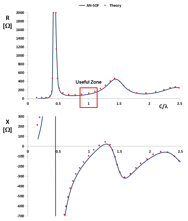
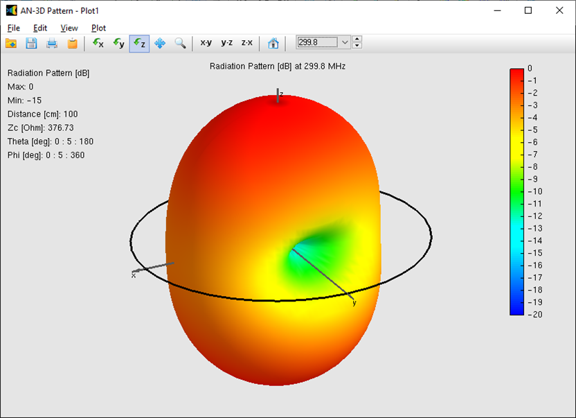
This behavior applies not only to circular loops but also to rectangular and square loops (quads). Therefore, for optimal performance, a quad antenna’s perimeter should be close to one wavelength (loop contour ≈ λ). Additionally, a single quad with a perimeter of one wavelength exhibits a radiation pattern similar to a “stretched donut,” offering broader coverage compared to a half-wave dipole (Figure 2). It’s important to note that the loop’s input impedance is also affected by the wire thickness (Ω in Figures 1 and 2). This parameter is proportional to the logarithm of the loop perimeter to wire radius ratio.
Achieving Directionality with a Quad Array
Having established the input impedance and radiation pattern of a single quad, we can explore how an array of multiple quads, arranged strategically, can achieve a directional pattern with a main beam. This concept is similar to Yagi-Uda antennas ( Yagis ) which consist of linear wire elements (dipoles) typically around half a wavelength long. By aligning these dipoles with decreasing lengths and spacing them strategically (0.2λ to 0.25λ), Yagis achieve a directional pattern with high gain in the desired direction. The specific element lengths and spacing are carefully chosen to optimize various parameters such as maximum gain in the main beam direction, minimum side lobes, front-to- back ratio, self-resonance, and overall efficiency.
Achieving directionality with a quad array is similar to Yagi antennas. The 5-element quad array used in this example consists of one director, one driven element (where the source is connected), and three additional directors.
Modeling a 5-Element Quad Array in AN-SOF
This article showcases an example of a 5-element quad array designed for the 2m band (145 MHz) using AN-SOF. This design serves as a reference point for future antenna development projects. As shown in Figure 3, the directional array is comprised of five quads, each with a perimeter close to one wavelength. However, the elements progressively decrease in size along the direction of maximum radiation.
The downloadable AN-SOF model (link below Figure 3) allows interested readers to extract the exact dimensions for potential construction of this antenna. Figure 3 also features an animation that demonstrates the variation of the 3D radiation pattern across a frequency sweep from 143 MHz to 148 MHz. This animation reveals that the back lobe decreases with increasing frequency, while the side lobes become more prominent.
One of the key benefits of this design is that it eliminates the need for a matching network. The VSWR curve in Figure 3 displays a clear dip at 145.7 MHz, indicating a good impedance match (around 50 Ohms) at the resonant frequency. The polar plot within the same figure showcases the gain in both horizontal (blue curve) and vertical (red curve) planes. The antenna boasts a maximum gain of approximately 12 dBi, a beam width of 50 degrees, and a front-to-back ratio of 20 dB at resonance.
Conclusion
This 5-element quad array modeled in AN-SOF demonstrates the potential for achieving good performance on the 2m band. The design offers several advantages, including:
- No external matching network required (due to the inherent impedance characteristics)
- Decent gain of 12 dBi
- Reasonable beam width of 50 degrees
- Favorable front-to-back ratio of 20 dB
While this design provides a solid foundation, it’s important to consider any limitations or practical implementation factors before construction. AN-SOF software offers a powerful tool for ham radio enthusiasts to model their own quad antenna designs, allowing them to experiment and achieve the desired performance characteristics for their specific needs.
