Search for answers or browse our Knowledge Base.
Guides | Models | Validation | Book
AN-SOF in Action: Modeling and Understanding the Performance of Fractal Antennas
Dive into the fascinating world of fractal antennas! This article explores their revolutionary design principles using AN-SOF simulation software. Discover how self-similar patterns unlock wider bandwidths, smaller sizes, and superior efficiency compared to traditional antennas.

Key Takeaways
- Compact Wideband Design: Fractal antennas like the snowflake quad achieve wide bandwidths in a surprisingly small size compared to traditional antennas.
- Array for Enhanced Performance: The article explores a 3-element array based on the snowflake fractal, potentially improving bandwidth compared to simpler designs.
- AN-SOF Simulation Advantage: AN-SOF software allows for simulating and optimizing the performance of complex fractal antenna structures.
Fractal Antennas: A Game-Changer in Antenna Design
The realm of antennas has seen a fascinating union between mathematics and engineering with the introduction of fractal antennas (Fig. 1). Fractals, once confined to the world of computer-generated imagery, have become a unifying principle in science, even linked to chaos theory.
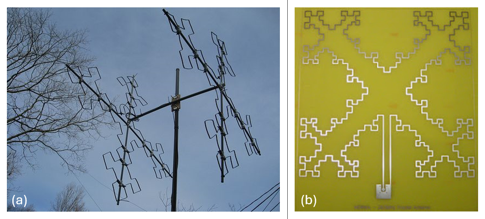
In the domain of antennas, fractals translate into powerful designs that boast high radiation efficiency, wider bandwidths, and minimized side lobes. A fractal antenna is essentially a radiating element that capitalizes on self-similar patterns to increase the effective perimeter of radiating material. This approach allows fractal antennas to be significantly smaller (50-75%) compared to traditional counterparts, while offering advantages in terms of reliability and cost-effectiveness.
The beauty of fractal designs lies in their versatility. They can be implemented across various existing antenna types, including dipoles, monopoles, patches, conformals, biconicals, discones, spirals, helicals, and even compact variants. This translates to benefits like multi-band operation, wide bandwidths, and a low-profile form factor. These characteristics make them ideal for applications with limited space and complex circuitry, and their robust nature has led to widespread adoption in military applications.
Unlike traditional antennas that require specific design features for each operating frequency, fractal antennas excel in their ability to operate effectively across multiple frequencies simultaneously. This stems from their underlying concept – a recursively generated geometry with fractional dimensions. Fractals possess intriguing properties, such as having a finite area yet an infinite perimeter.
Practical Applications and Promising Potential
The future of wireless communication holds immense promise for fractal antennas. They offer the potential for robust and efficient communication systems with a reduced number of antenna elements. This makes them suitable for both individual antennas and antenna arrays.
Experimental Validation
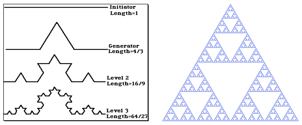
Experiments conducted with fractal antenna designs, such as the Koch curve and Sierpinski triangle (Fig. 2), have yielded impressive results. These trials have demonstrated improved performance, wider transmission bands, and the potential to eliminate the need for matching circuits.
A Deeper Dive
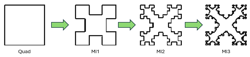
In the article “The Fractal Antenna” by Angel Vilaseca, HB9SLV, fractalization of the Quad antenna is explained (VHF Communications, Vol. 33, pp. 213-226, 2001-Q4). Vilaseca’s article dives into the design sequence of the Quad antenna transforming through the first three stages (MI1, MI2, and MI3) of the Minkowski square fractalization (Fig. 3). It also presents experimental results by Nathan Cohen, N1IR, for an array of two MI2 elements designed for the 10m band.
In the next section, we’ll delve into AN-SOF modeling using a specific example – an MI2 fractal quad loop.
Modeling the MI2 Fractal Loop with AN-SOF
The MI2 Fractal Loop antenna is a pioneering design by Dr. Nathan Cohen, documented in his research paper co-authored with R.G. Hohlfeld titled “Fractal Loops and the Small Loop Approximation” (Communications Quarterly, Vol. 6, pp. 77-81, 1996). This design offers a compelling example of how fractal geometry translates into practical antenna benefits.
According to Cohen’s report, the MI2 Fractal Loop boasts an input resistance of 26 Ohms and a gain of 2 dBi at its first resonant frequency in the 20m band. This design achieves a desirable resonant resistance within a reduced physical size.
AN-SOF Simulation Results
Our AN-SOF simulation results for the MI2 Fractal Loop antenna are consistent with the published data. The first resonance occurs between 15.33 and 15.34 MHz, with an input resistance of 28 Ohms, closely aligned with the reported value. The simulated antenna gain is 1.90 dBi, demonstrating good agreement with Cohen’s findings.
The 2:1 VSWR bandwidth, a crucial parameter indicating efficient power transfer, is 1.04% in our simulation. The model itself has a compact size of 2.8 x 2.662 meters, showcasing the space-saving potential of fractal designs. However, it’s important to note that the total wire length of the MI2 antenna is 27.56 meters, which corresponds to 1.38 times its design wavelength (λ = 20 meters).
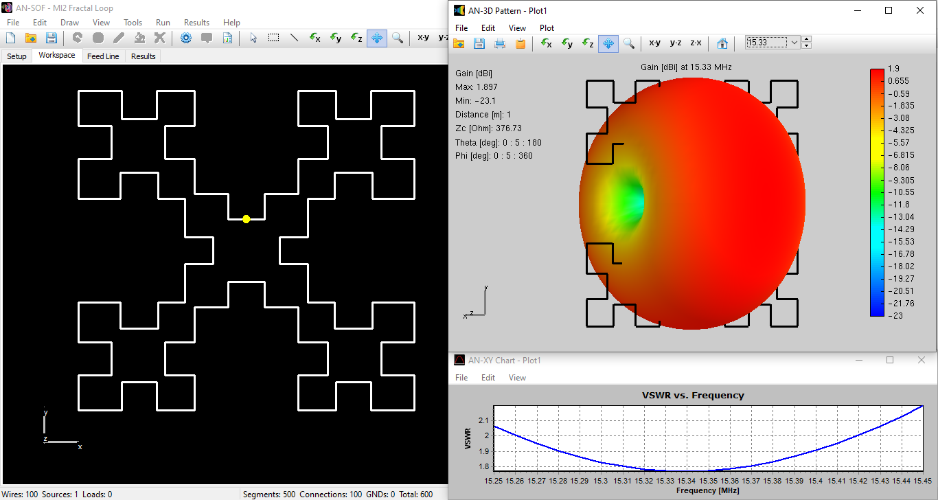
Figure 4 presents a comprehensive view of the MI2 model within the AN-SOF workspace (left). The image also showcases the 3D radiation pattern obtained from the simulation, which resembles the donut-shaped pattern characteristic of a short dipole antenna. Finally, the VSWR curve on the right visually depicts the bandwidth where the VSWR remains below 2, ranging from 15.26 to 15.42 MHz.
Next Steps
This analysis of the MI2 Fractal Loop antenna using AN-SOF serves as a springboard for further exploration. In the next section, we’ll simulate a 3-element array of MI2 loops, aiming to achieve potentially increased bandwidth compared to Dr. Cohen’s original 2-element design.
Expanding the Potential: 3-Element Array of Snowflake Quads
The MI2 fractal loop antenna is also known as the snowflake quad. This section explores a concept that expands on Dr. Cohen’s work: a 3-element array derived from this snowflake fractal design.
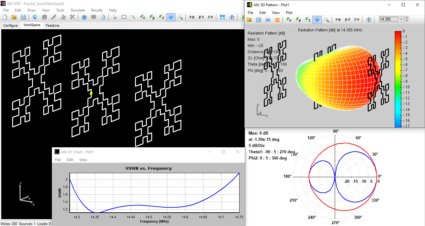
The AN-SOF model and simulation results in Fig. 5 are particularly noteworthy. Our simulations demonstrate that a 3-element array can nearly double the reported bandwidth of a 2-element MI2 Fractal Loop antenna. This improvement stems from the array configuration, which utilizes a strategically placed reflector, driven element, and director to optimize performance.
Compelling Performance in the 20m Band
Here’s a breakdown of the simulated performance for the 3-element array operating in the 20m band (around 14 MHz):
- Compact Quad Size: Each quad element measures approximately 290 x 290 cm, representing a mere 0.14 x 0.14 wavelength footprint.
- Optimized Element Spacing: The elements within the array are spaced at roughly 280 cm for optimal signal interaction.
- Wide Bandwidth: The simulated results indicate a substantial bandwidth of 450 kHz (VSWR < 2), centered around 14.5 MHz. This translates to a notable improvement over 2-element designs.
- Balanced Gain and Front-to-Back Ratio: The array exhibits a gain of 6 dBi, while maintaining a front-to-back ratio of 10 dB.
- Beamwidth and Polarization: The simulated beamwidth of the array is approximately 80°, making it suitable for various communication applications. The antenna maintains vertical polarization for consistent signal orientation.
Practical Advantages and Considerations
While the 3-element array might not achieve the same level of gain as a larger 3-element Yagi-Uda antenna, it offers a compelling trade-off. The fractal design delivers a remarkably wide bandwidth within a very compact size. Additionally, it eliminates the need for a matching circuit, as its impedance is simulated to be 50 Ohms at resonance, allowing for direct connection to a 50 Ohm coaxial cable. This translates to a simpler and potentially lower-cost antenna system.
Figure 5 provides a comprehensive view of this design. On the left, the 3-element array is shown within the AN-SOF workspace. The right side displays the radiation pattern, and the bottom left corner presents the VSWR curve, which visually represents the bandwidth where the VSWR remains below 2.
Scaling the Snowflake Quad for Different Bands
To design a snowflake quad antenna for a band other than the 20m example, we simply need to rescale the antenna dimensions. For instance, to operate in the 10m band (around 30 MHz), you would divide the model dimensions by 2.
AN-SOF makes rescaling straightforward using the Scale Wires command (Fig. 6). Here’s how to do it:
- Click the “Selection Box” button on the AN-SOF toolbar and draw a box that encompasses the entire antenna.
- Navigate to the main menu: Edit > Scale Wires.
- Set the scale factor to 0.5 to halve the antenna dimensions.
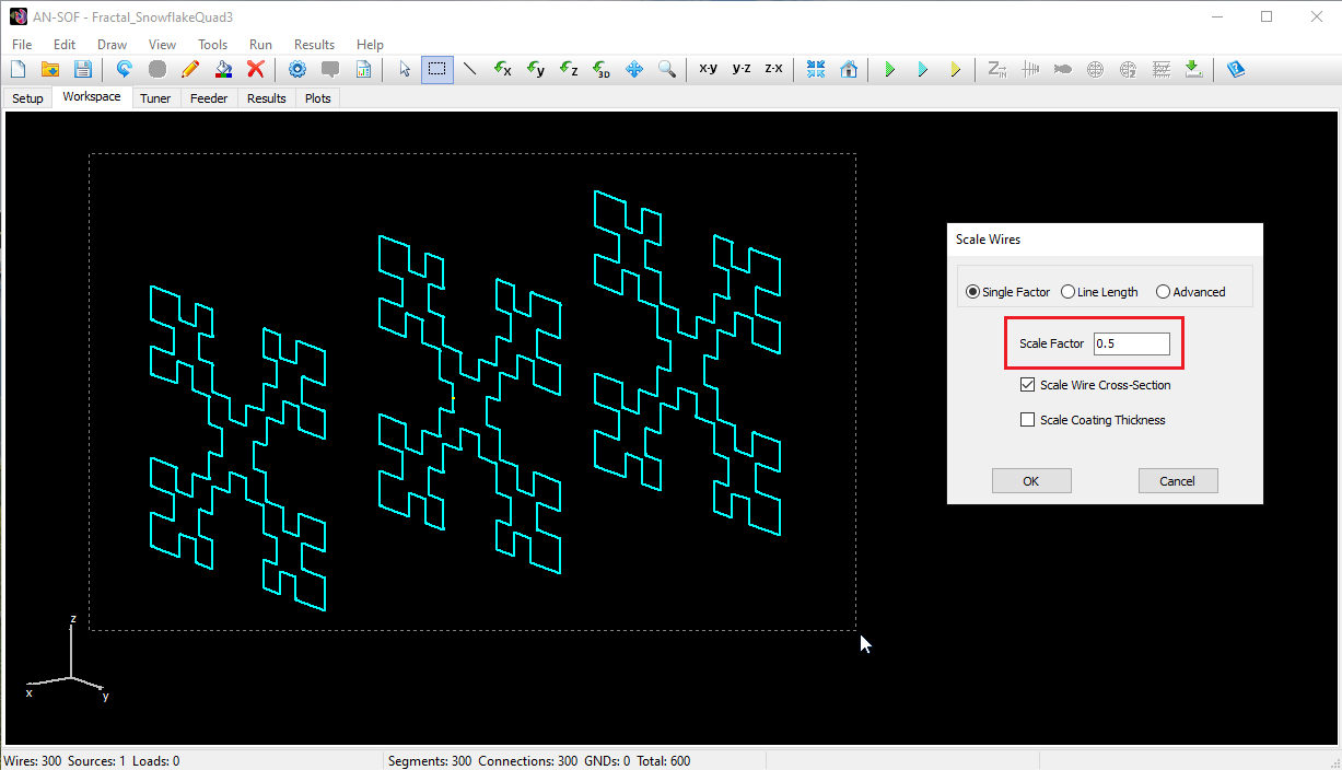
Optionally, you can also scale the wire cross-section radius. However, it’s important to note that if you don’t scale the wire thickness, the resonance frequency in the 10m band won’t be precisely double the 20m band’s resonance. This is because the wire thickness affects the antenna’s input impedance.
Looking Ahead
The 3-element snowflake quad array exemplifies the potential of fractal antennas to deliver exceptional performance within compact and practical designs. In the next section, we’ll conclude by summarizing the key takeaways and exploring exciting future directions for fractal antenna research.
Concluding Remarks
This final section serves to summarize the key takeaways from our exploration of fractal antennas and address some frequently asked questions.
1. Fractal Concept: Unveiling the Beauty of Complexity
At their core, fractals are self-similar patterns that exhibit intricate detail at every scale. Imagine a coastline – as you zoom in, you discover smaller and smaller coves and inlets that resemble the overall shape of the entire coastline. This concept of infinite complexity within a bounded structure is a hallmark of fractals.
While chaos theory delves into seemingly random systems exhibiting underlying order, the connection to fractals is more philosophical. Fractals, with their intricate self-similarity, can sometimes represent the unpredictable behavior observed in chaotic systems. However, not all fractals are inherently chaotic.
2. Antenna Application: When Geometry Gets Smart
The magic of fractal antennas lies in their ability to leverage these self-similar patterns to increase the electrical length of an antenna within a compact physical size. This translates to several advantages:
- Wider Bandwidths: Fractal designs can achieve a broader range of operational frequencies compared to traditional antennas of similar size.
- Enhanced Efficiency: The increased electrical length improves radiation efficiency, leading to stronger signal transmission and reception.
- Reduced Size: Fractal antennas can be significantly smaller than their traditional counterparts, making them ideal for applications with limited space constraints.
3. Practical Examples: Fractals in Action
The MI2 Fractal Loop antenna exemplifies the potential of fractal designs. It offers a desirable resonant resistance within a compact form factor. Additionally, the 3-element snowflake quad array demonstrates how fractal geometries can be used to create arrays with impressive bandwidth and front-to-back ratios.
Beyond these examples, fractal design principles can be applied to various antenna types, including dipoles, monopoles, and patches. This versatility opens doors for innovation across a wide range of antenna applications.
In Conclusion
Fractal antennas represent a fascinating and revolutionary approach to antenna design. Their ability to achieve superior performance within compact sizes makes them ideal for a wide range of applications, from mobile communication to military technology. As research in this field continues to evolve, we can expect to see even more innovative and efficient fractal antenna designs emerge in the years to come.
