Search for answers or browse our Knowledge Base.
Guides | Models | Validation | Book
Validating V Antennas: Directivity Analysis with AN-SOF
This article validates AN-SOF’s results against established formulas for V antennas, highlighting its advanced modeling capabilities. We explore optimal angles, directivity enhancements, and precise calculations, making AN-SOF a powerful tool for RF engineers, ham radio enthusiasts, and antenna designers.
Introduction
The V antenna is a type of traveling wave antenna known for its ability to achieve high directivity, especially when the length of each leg of the V is greater than the wavelength. This configuration allows for effective radiation of signals, making it a popular choice in various applications:
- Military Communications: V antennas are frequently used in military communication systems due to their high directivity and the ability to operate over a wide range of frequencies. Their design allows for long-range communication, which is crucial in military operations.
- Amateur Radio: Ham radio enthusiasts often use V antennas for their versatility and performance. These antennas are relatively easy to construct and can be adjusted to cover different frequency bands, making them ideal for amateur radio applications. Nevertheless, due to the decline in the use of radio communications on HF bands, the V antenna has become rarely used in modern amateur radio practices.
- Broadcasting: V antennas are used in broadcasting, especially in medium and shortwave radio stations. Their ability to produce a strong, directional signal makes them suitable for reaching distant audiences.
The purpose of this article is to validate AN-SOF results against well-established formulas for V antennas, providing a comprehensive comparison and showcasing the accuracy and advancements offered by AN-SOF.
Optimum Angle and Directivity Formulas
The angle between the legs must be chosen so that the fields radiated by both legs constructively add in the forward direction. Several authors have investigated the optimum angle of the V antenna as a function of the length of its legs. For instance, refer to G. A. Thiele and E. P. Ekelman, Jr., “Design Formulas for Vee Dipoles,” IEEE Trans. Antennas Propagat., Vol. AP-28, No. 4, pp. 588–590, July 1980.
Thiele and Ekelman have provided a formula for calculating the angle between the legs that maximizes the directivity of a symmetric V antenna. This angle, $\theta$, depends on the length of the leg measured in wavelengths, $L/\lambda$, and is given by:
$\displaystyle \theta = -149.3 \, \left( \frac{L}{\lambda} \right)^3 + 603.4 \, \left( \frac{L}{\lambda} \right)^2 – \, 809.5 \, \frac{L}{\lambda} + 443.6 \quad \text{for} \quad 0.5 \leq L/\lambda \leq 1.5 \qquad (1a)$
or
$\displaystyle \theta = 13.39 \, \left( \frac{L}{\lambda} \right)^2 – \, 78.27 \, \frac{L}{\lambda} + 169.77 \quad \text{for} \quad 1.5 \leq L/\lambda \leq 3 \qquad (1b)$
where $\theta$ is in degrees.
This formula is a polynomial fit to the results of various simulations using the Method of Moments (MoM). A linear fit to maximum directivity as a function of leg length has also been reported and is given by:
$\displaystyle D = 2.94 \,\, \frac{L}{\lambda} \, + \, 1.15 \quad \text{for} \quad 0.5 \leq \frac{L}{\lambda} \leq 3 \qquad (2)$
where $D$ is the maximum directivity (dimensionless, not in decibels) obtained for a given leg length $L/\lambda$, when the angle $\theta$ between the V antenna legs is given by formula (1).
Details of the segmentation and kernel of the integral equation used have not been provided, but it is likely that the thin-wire approximation was used. Despite these missing details, these formulas serve as a reference to compare with the results obtained from AN-SOF and are implemented in the V antenna calculator below.
V-Antenna Calculator
Enhanced Directivity Analysis with AN-SOF
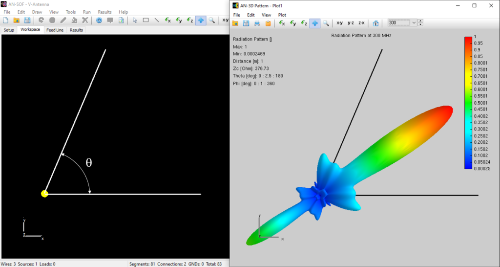
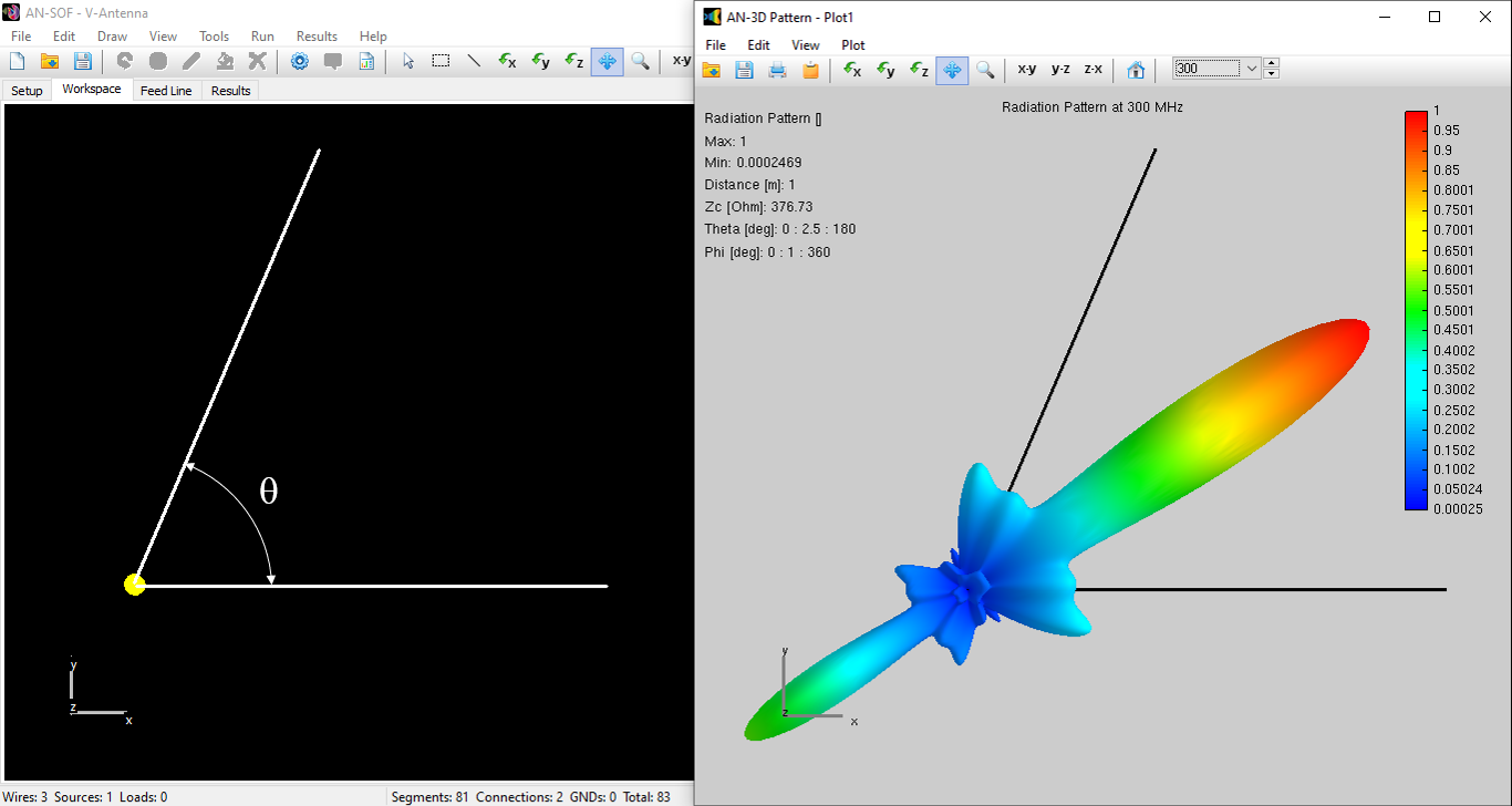
Figure 1 illustrates the AN-SOF model of a V antenna along with the calculated radiation pattern for a leg length of $L/\lambda = 2$ and an angle $\theta = 67^\circ$. Figure 2 presents the maximum directivity as a function of the leg length in wavelengths. The comparison shows a good agreement between the two approaches.
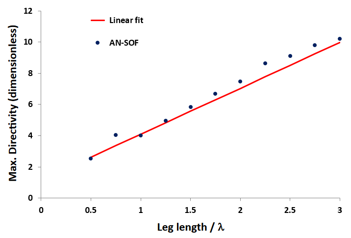
The values derived from Equation (2) are slightly lower than those obtained from AN-SOF, indicating a shorter effective antenna leg length. This shift is a known effect when comparing results from traditional thin-wire approximation methods of moments (MoM) with those using the exact kernel method. Therefore, this discrepancy is expected and observed in these comparisons.
Concluding Remarks
The V antenna, with its high directivity, remains a valuable tool in the field of antenna engineering, despite its reduced usage in modern amateur radio practices. Through detailed analysis and comparison, it is evident that the implementation of advanced techniques such as the Exact Kernel method in AN-SOF significantly enhances the accuracy of antenna modeling. The results obtained using AN-SOF demonstrate a closer alignment with theoretical predictions and offer improved performance over traditional thin-wire approximations.
