Search for answers or browse our Knowledge Base.
Guides | Models | Validation | Book
Design and Simulation of Short Top-Loaded Monopole Antennas for LF and MF Bands
This article explores the design and simulation of compact top-loaded monopole antennas for LF and MF bands, highlighting efficiency optimization through top-loading and radial ground screens using AN-SOF. Ideal for AM broadcasting and low-frequency communications.
Improving Radiation Efficiency in Compact Top-Loaded Monopole Antennas
Short antennas have recently garnered renewed interest within the broadcasting and communications sectors, particularly for use in the Low Frequency (LF) and Medium Frequency (MF) bands. While top-loaded monopoles have been in use since the 1920s, they remain the preferred solution for applications requiring a compact vertical antenna with adequate performance tailored to modern broadcasting and communication demands.
Top-loading enhances the electrical height of a physically short monopole, effectively increasing its radiation resistance and overall radiation efficiency. In the LF and MF bands, where antennas are typically electrically short, improving the conductivity of the ground beneath the antenna is essential. This is usually achieved by deploying a ground screen composed of radial wires, either buried or laid directly on the soil surface, which significantly reduces ground loss resistance and improves overall efficiency.
When properly dimensioned, short top-loaded monopole antennas can approach the performance of a standard quarter-wave monopole. Therefore, optimizing both the antenna structure and the radial ground system, by adjusting the number and length of radials, is crucial for maximizing radiation efficiency and achieving strong field strength across different soil conditions.
With proper design, such antennas can offer a simple yet highly efficient solution for AM or digital broadcasting in the MF band, as well as intelligible speech transmission in the LF band, providing the broadcasting and communication communities with a reliable low-profile alternative.
Configurations of Top-Loaded Monopole Antennas
A top-loaded monopole antenna incorporates one or more horizontal wire elements connected to the upper end of a vertical radiator. These horizontal elements, positioned parallel to the ground surface, serve both electrical and mechanical purposes, significantly influencing antenna performance.
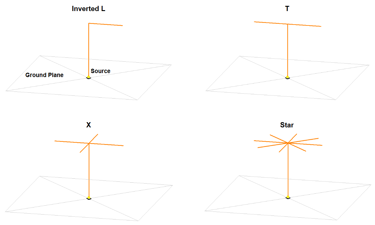
When a single horizontal wire is used, the structure forms an Inverted-L antenna. Adding a second branch results in a T antenna, while four evenly spaced branches produce what is known as an X antenna. If more than four branches are connected radially at the top of the monopole, the configuration becomes a Star antenna (Fig. 1).Top-loaded monopoles are widely used in Amplitude Modulated (AM) broadcast systems. In addition to increasing radiation resistance, the top-loading structure plays a key role in tuning the antenna to resonance. This is achieved by carefully selecting the lengths of the horizontal wires, optimizing the current distribution and electrical characteristics of the antenna.
Simulation of an X-Type Top-Loaded Monopole at 1 MHz
In this simulation example, we consider an “X” top-loaded monopole antenna operating at 1 MHz, a typical frequency in the Medium Frequency (MF) band used for AM broadcasting. At this frequency, the wavelength is approximately 300 meters. The vertical radiator is modeled with a height of 0.1λ (30 m), and each of the four top-loading wires is 0.062λ (18.5 m) long, dimensioned to achieve resonance by effectively cancelling the imaginary component of the input impedance. The antenna is fed at its base, as is standard for monopole configurations.
To configure the ground plane in AN-SOF, navigate to the Setup tab, open the Environment panel, and select “Real” as the ground type. Within the Real Ground Options, choose “Radial Wire Ground Screen”. Here, you can select a predefined soil model with specific conductivity and relative permittivity (dielectric constant), and specify the number of radials, their length, and wire radius. The parameters used in this example are illustrated in Fig. 2(a).
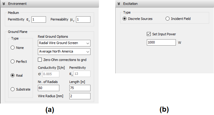
For consistency with typical broadcast system evaluations, an input power of 1 kW is applied. In the Excitation panel, select “Discrete Sources”, enable “Set Input Power”, and enter 1,000 W, as shown in Fig. 2(b).
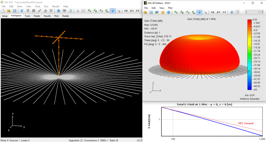
Figure 3 (left) displays the antenna geometry within AN-SOF’s workspace. The number of segments has been globally adjusted to ensure a minimum of 20 segments per wavelength for accuracy. For efficient editing, refer to the guide titled New Tools in AN-SOF: Selecting and Editing Wires in Bulk for modifying attributes across multiple wires.
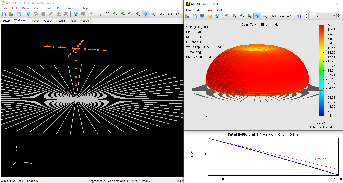
The gain pattern, shown in Fig. 3 (top right), is symmetric about the vertical axis, with a null along that axis, as expected for a monopole. At ground level, the radiation is also minimal due to ground wave attenuation caused by soil losses. This loss is reflected in the peak gain of 0.53 dBi, a substantial reduction compared to the theoretical 5.16 dBi gain of a short monopole over a perfect electric conductor (PEC) ground.Additionally, Fig. 3 (bottom right) presents the electric field strength (E-field) in V/m as a function of distance from the antenna base, plotted on logarithmic axes. The red straight line in the plot represents the ideal 1/r decay, valid for a lossless ground. In this simulation, the near-field region is evaluated from 75 m (λ/4) to 1 km. A common performance metric is the field strength at 1 km, referenced to 1 kW of input power.
Input Impedance and Radiation Efficiency Considerations
The input impedance of the simulated antenna is approximately 20 – j 1 Ω, which indicates that the structure is effectively resonant. While a 20-ohm resistive input might seem low, it’s a significant improvement over the same monopole without top-loading, where the impedance drops to around 10 – j 630 Ω, a highly reactive and inefficient configuration. This comparison underscores the role of top-loading not only in achieving resonance (by minimizing reactance) but also in increasing the radiation resistance, thereby enhancing the power radiated.
In practical installations, supporting structures such as vertical poles with insulators are used to suspend the top-loading wires above ground, ensuring they are electrically isolated from the support system and do not short to ground.
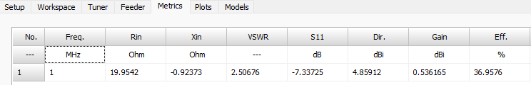
Figure 4 displays a snapshot of the Metrics tab in AN-SOF, where the input impedance and key radiation parameters are listed. The radiation efficiency is calculated to be 37%, which is relatively low but typical for short monopoles over real ground, especially in the MF and LF bands. This limited efficiency is largely due to ground losses, which can be mitigated by employing a radial wire ground screen.
However, since practical constraints limit the number and length of radial wires, the ground plane can only be improved to a certain extent. While extending the radials beyond λ/4 could further reduce loss resistance, it is often impractical and cost-prohibitive in real-world installations.
Conclusions
Top-loaded short monopole antennas are a practical solution for achieving efficient radiation at LF and MF frequencies where full-size structures are often unfeasible. By carefully designing the top-loading configuration and incorporating a radial ground screen, it is possible to approach the performance of a quarter-wave monopole while maintaining a compact form factor. Although radiation efficiency is inherently limited by ground losses, proper optimization of antenna geometry and ground system parameters can yield satisfactory results for both AM broadcasting and low-frequency communication applications.
