Search for answers or browse our Knowledge Base.
Guides | Models | Validation | Book
AN-SOF Antenna Simulation Best Practices: Checking and Correcting Model Errors
When creating an antenna model or a wire structure in the AN-SOF workspace, several crucial aspects must be considered to ensure the model’s validity. Particularly, when dealing with complex structures composed of numerous wires, the possibility of errors arises. However, AN-SOF provides three essential commands that can be executed in any order and whenever needed to aid in error detection within the model. These commands can be accessed by navigating to the AN-SOF main menu and selecting Tools, Fig. 1, where the following options are available:

Checking Individual Wires
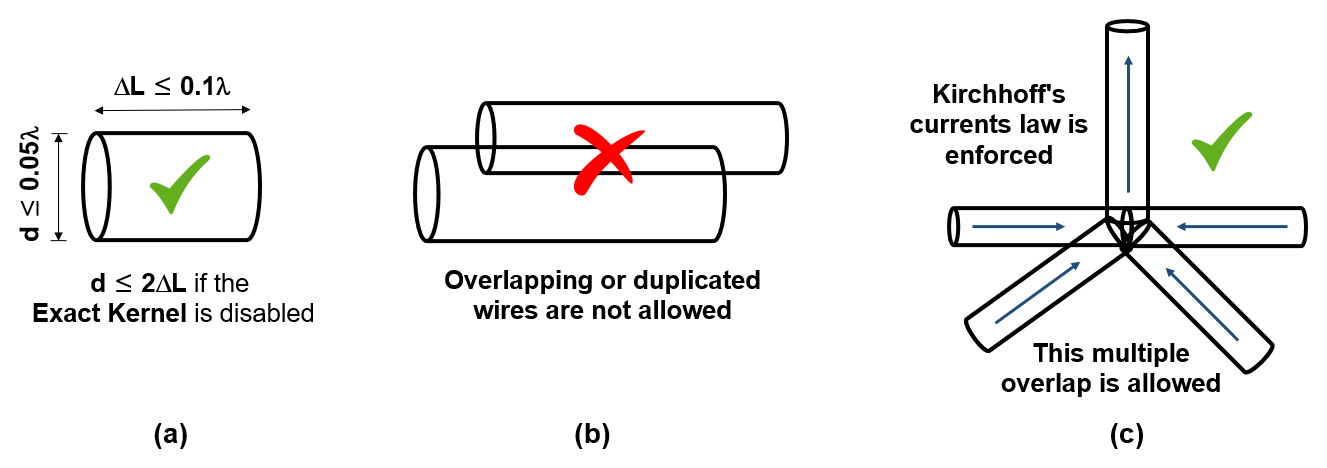
The Check Individual Wires command performs a comprehensive assessment of three essential parameters associated with each wire individually. Wires with errors will be highlighted in red, while those with warnings will be highlighted in yellow. The parameters subjected to evaluation are illustrated in Fig. 2(a) and are as follows:
- Segment Length / Shortest Wavelength (ΔL/λmin): This parameter examines the ratio between each wire segment’s length, ΔL, and the shortest wavelength, λmin, within the frequency sweep. It is essential to ensure that the segment length is sufficiently small compared to the shortest wavelength, representing the worst-case scenario. The criteria defining whether a wire is considered “OK,” “Warning,” or “Error” are as follows:
- ΔL/λmin ≤ 0.1 → The wire is considered OK.
- 0.1 < ΔL/λmin ≤ 0.2 → The wire is marked as a warning.
- ΔL/λmin > 0.2 → The wire is identified as having an error.
- Cross-Section Size / Shortest Wavelength (d/λmin): This parameter focuses on the wire’s cross-section diameter, d, relative to the shortest wavelength, λmin, within the frequency sweep. If the wire’s cross-section is not circular, the equivalent radius is calculated to determine the diameter. The cross-section of each wire must be sufficiently small compared to the wavelength. The criteria for evaluating a wire’s status are as follows:
- d/λmin ≤ 0.05 → The wire is considered OK.
- 0.05 < d/λmin ≤ 0.1 → The wire is marked as a warning.
- d/λmin > 0.1 → The wire is identified as having an error.
- Thin-Wire Ratio (Segment Diameter / Length): This parameter is particularly relevant when increasing the segmentation in a given wire for purposes such as convergence analysis. As the segmentation increases, the segment lengths decrease, causing each segment to become “thicker” in the sense that its diameter, d, approaches its length, ΔL. AN-SOF provides two different Kernels for calculations: the default Exact Kernel, which allows precise calculations on very thick wires, and the Extended Kernel designed for wire segments with a diameter up to 3 times their length (d/ΔL = 3). If the Exact Kernel is not enabled in the Setup tab > Settings, the segment diameter-to-length ratio, d/ΔL, will be checked. This ratio is referred to as the “thin-wire ratio,” and the evaluation criteria are as follows:
- d/ΔL ≤ 2 → The wire is considered OK.
- 2 < d/ΔL ≤ 3 → The wire is marked as a warning.
- d/ΔL > 3 → The wire is identified as having an error.
Errors associated with a wire segment that is too long (ΔL/λmin > 0.2) can be easily rectified by increasing the number of segments for the affected wire. However, it is crucial to enable the “Exact Kernel” option when significantly increasing the number of segments, as each segment becomes thicker. Only disable the Exact Kernel when prioritizing computational speed over accuracy.
For cases involving very thick wires (d/λmin > 0.1), it is advisable to represent them using a cylinder composed of a grid of wires, instead of a single wire.
By conducting these individual wire checks, users can proactively identify and address any potential issues related to wire segment length, cross-section size, and thin-wire ratios within their antenna models, ensuring accurate and reliable simulation results.
Checking Wire Spacing
The Check Wire Spacing command plays a critical role in verifying that each wire within the model does not overlap with others, Fig. 2(b). The proximity between two wires is permitted as long as their radii allow it, without resulting in an actual overlap. Wires found to be in error due to overlapping will be highlighted in red, while those with warnings will be marked in yellow. In cases where multiple wires’ ends are connected at a common point, as Fig. 2(c) shows, overlaps may be detected and categorized as errors or warnings. However, it is important to note that such overlaps do not adversely affect the simulation calculations, as long as the limits specified in the previous evaluation items are adhered to.
At points where multiple wires are interconnected, AN-SOF ensures that Kirchhoff’s currents law is strictly enforced. This law states that the algebraic sum of currents meeting at a point must be zero. By fulfilling this requirement, AN-SOF effectively eliminates any errors that could potentially arise due to overlapping between wires.
In summary, the Check Wire Spacing command serves to identify and flag any instances of wire overlap, providing a visual indication of errors or warnings. Nevertheless, it is reassuring to know that such overlaps, particularly at points where multiple wires converge, do not compromise the accuracy of the calculations, as AN-SOF guarantees the fulfillment of Kirchhoff’s currents law at these interconnected points.
Deleting Duplicate Wires
The Delete Duplicate Wires command serves the crucial purpose of identifying and removing any duplicate wires present within the model. A duplicate wire is defined as one that completely overlaps another wire along its entire length. In the case of linear wires, mere coincidence of their endpoints is sufficient for them to be duplicates. Such duplicates are not permissible in a model because they lead to a singular matrix in the Method of Moments, analogous to repeating an equation in a system of linear equations. Running this command ensures the elimination of all duplicate wires from the model.
To ensure a robust and accurate simulation, it is considered a best practice to check specifically for duplicate wires before initiating any calculations.
In summary, we have explored crucial commands for detecting and correcting errors in AN-SOF antenna simulations. “Check Individual Wires” validates wire parameters, such as segment length, cross-section size, and thin-wire ratio, ensuring model integrity. “Check Wire Spacing” identifies overlaps between wires, essential for precise simulations. “Delete Duplicate Wires” eliminates redundancy, preventing singular matrices in calculations. By adopting these practices, users can achieve robust simulations, enhancing the accuracy and reliability of AN-SOF antenna models.