Search for answers or browse our Knowledge Base.
Guides | Models | Validation | Book
Front-to-Rear and Front-to-Back Ratios: Applying Key Antenna Directivity Metrics
Understand the difference between Front-to-Rear (F/R) and Front-to-Back (F/B) ratios, key metrics for antenna directivity. Learn how to calculate and interpret these values using AN-SOF software. Improve your antenna designs with this essential knowledge.
Two commonly used metrics for quantifying the directional properties of an antenna radiation pattern are the front-to-rear ratio (F/R) and the front-to-back ratio (F/B). Both F/R and F/B are crucial parameters for evaluating antenna performance, especially in applications requiring high directivity and low interference, such as point-to-point communication links and satellite systems.
- Front-to-Rear (F/R) Ratio: The ratio of the maximum power density radiated in the forward direction ($0^\circ$) to the peak power density found anywhere within the entire rear hemisphere (typically $90^\circ$ to $270^\circ$). This serves as a “worst-case” performance metric, indicating how effectively the antenna suppresses unwanted radiation or interference across the entire back half of its pattern. In simulators like AN-SOF, this value is critical for assessing the overall cleanliness of a directional radiation pattern.
- Front-to-Back (F/B) Ratio: The ratio of the maximum power density in the forward direction ($0^\circ$) to the power density radiated precisely in the opposite direction ($180^\circ$). This is a point-specific measurement that characterizes the antenna’s isolation from signals coming directly from behind it. Unlike the F/R ratio, it does not account for secondary lobes or “hot spots” elsewhere in the rear hemisphere. These parameters can be analyzed alongside gain and directivity in the software’s Metrics tab.
Both F/R and F/B are typically expressed in decibels (dB).
| Metric | Definition |
|---|---|
| F/R (Worst-case Front-to-Back) | Ratio of maximum forward power density to maximum backward power density |
| F/B (180°-Front-to-Back) | Ratio of maximum forward power density to power density at 180 degrees |
Figure 1 illustrates the difference between F/R and F/B, assuming a 360-degree radiation pattern slice.
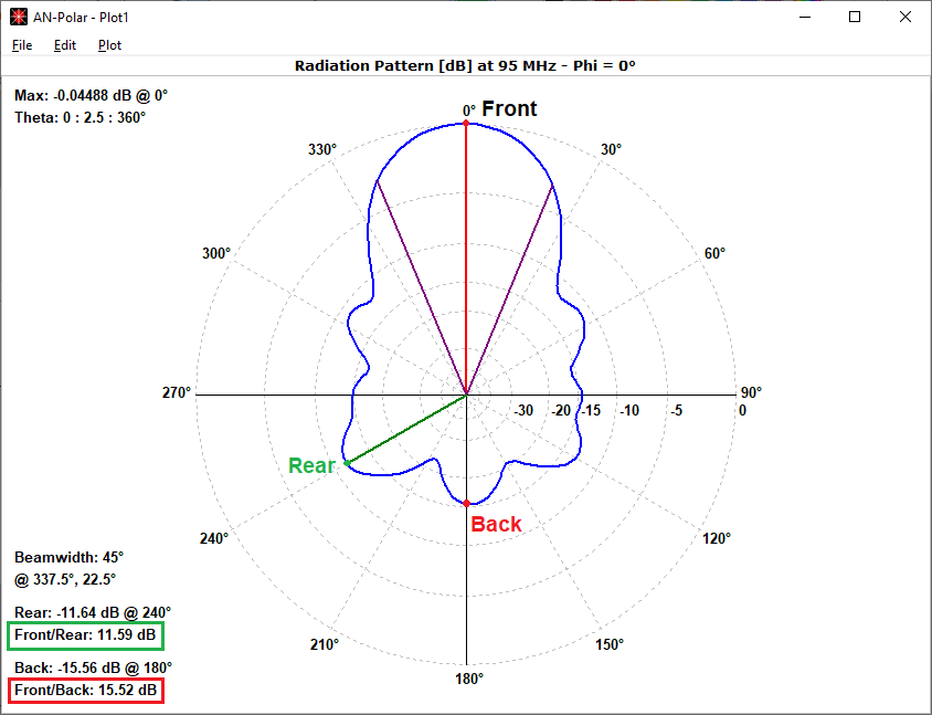
In summary, the primary distinction between F/R and F/B lies in the direction of backward radiation. F/R compares the maximum forward power density to the maximum backward power density, while F/B compares the maximum forward power density to the power density radiated in the opposite direction.
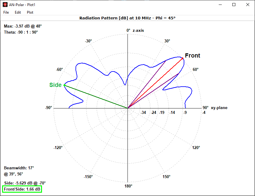
These definitions are applicable to both horizontal (θ = const.) and vertical (φ = const.) radiation patterns in free space. However, the presence of a ground plane introduces complexities. For horizontal patterns, F/R and F/B calculations remain unchanged as the angular range spans 360 degrees. Conversely, for vertical patterns, the angular range is limited to 180 degrees. In this case, F/R is redefined as the front-to-side ratio, comparing the maximum signal to the maximum signal in the opposite quadrant (as depicted in Fig. 2). F/B becomes irrelevant due to the absence of a ‘back’ direction for an infinite ground plane, resulting in a zero value from AN-SOF.
Understanding F/R and F/B is crucial for effective antenna design. The Metrics tab in the AN-SOF main window presents F/R and F/B values in dB as a function of frequency for both vertical (V) and horizontal (H) radiation pattern slices. The Plots tab offers a visual comparison of F/R and F/B over the frequency range.
📝 Note:
- To ensure proper calculations of F/R and F/B, select the Full 3D, Vertical or Horizontal options in the Far-Field panel.
- Selecting the Custom option in the Far-Field panel will lead to variations in the calculation of F/R and F/B as they will depend on the specific angular ranges that have been configured.
See Also:
Technical Keywords: Front-to-Rear Ratio (F/R), Front-to-Back Ratio (F/B), Antenna Directivity, Radiation Pattern, Power Density, Interference Suppression, Antenna Performance Evaluation, Horizontal Pattern, Vertical Pattern, Free Space, Ground Plane, Front-to-Side Ratio, Worst-case Performance Metric, Point-to-Point Communication.
