Search for answers or browse our Knowledge Base.
Guides | Models | Validation | Blog
-
Guides
-
-
- Complete Workflow: Modeling, Feeding, and Tuning a 20m Band Dipole Antenna
- DIY Helix High Gain Directional Antenna: From Simulation to 3D Printing
- Evaluating EMF Compliance - Part 1: A Guide to Far-Field RF Exposure Assessments
- Design Guidelines for Skeleton Slot Antennas: A Simulation-Driven Approach
- Simplified Modeling for Microstrip Antennas on Ungrounded Dielectric Substrates: Accuracy Meets Simplicity
- Fast Modeling of a Monopole Supported by a Broadcast Tower
- Linking Log-Periodic Antenna Elements Using Transmission Lines
- Wave Matching Coefficient: Defining the Practical Near-Far Field Boundary
- AN-SOF Mastery: Adding Elevated Radials Quickly
- Enhancing Antenna Design: Project Merging in AN-SOF
- On the Modeling of Radio Masts
- The Equivalent Circuit of a Balun
- AN-SOF Antenna Simulation Best Practices: Checking and Correcting Model Errors
-
-
- AN-SOF 9: Taking Antenna Design Further with New Feeder and Tuner Calculators
- AN-SOF Antenna Simulation Software - Version 8.90 Release Notes
- AN-SOF 8.70: Enhancing Your Antenna Design Journey
- Introducing AN-SOF 8.50: Enhanced Antenna Design & Simulation Software
- Get Ready for the Next Level of Antenna Design: AN-SOF 8.50 is Coming Soon!
- Explore the Cutting-Edge World of AN-SOF Antenna Simulation Software!
- Upgrade to AN-SOF 8.20 - Unleash Your Potential
- AN-SOF 8: Elevating Antenna Simulation to the Next Level
- New Release: AN-SOF 7.90
- AN-SOF 7.80 is ready!
- New AN-SOF User Guide
- New Release: AN-SOF 7.50
- AN-SOF 7.20 is ready!
- New Release :: AN-SOF 7.10 ::
- AN-SOF 7.0 is Here!
- New Release :: AN-SOF 6.40 ::
- New Release :: AN-SOF 6.20 ::
- Show All Articles2 Collapse Articles
-
-
-
-
Models
-
- Modeling a Super J-Pole: A Look Inside a 5-Element Collinear Antenna
- Simulating the Ingenious Multiband Omnidirectional Dipole Antenna Design
- The Loop on Ground (LoG): A Compact Receiving Antenna with Directional Capabilities
- Precision Simulations with AN-SOF for Magnetic Loop Antennas
- Advantages of AN-SOF for Simulating 433 MHz Spring Helical Antennas for ISM & LoRa Applications
- Radio Mast Above Wire Screen
- Square Loop Antenna
- Receiving Loop Antenna
- Monopole Above Earth Ground
- Top-Loaded Short Monopole
- Half-Wave Dipole
- Folded Dipole
- Dipole Antenna
- The 5-in-1 J-Pole Antenna Solution for Multiband Communications
-
- Extended Double Zepp (EDZ): A Phased Array Solution for Directional Antenna Applications
- Transmission Line Feeding for Antennas: The Four-Square Array
- Log-Periodic Christmas Tree
- Enhancing VHF Performance: The Dual Reflector Moxon Antenna for 145 MHz
- Building a Compact High-Performance UHF Array with AN-SOF: A 4-Element Biquad Design
- Building a Beam: Modeling a 5-Element 2m Band Quad Array
- Broadside Dipole Array
- Log-Periodic Dipole Array
- Broadband Directional Antenna
- A Closer Look at the HF Skeleton Slot Antenna
- The 17m Band 2-Element Delta Loop Beam: A Compact, High-Gain Antenna for DX Enthusiasts
- Enhancing Satellite Links: The Moxon-Yagi Dual Band VHF/UHF Antenna
-
Validation
-
-
- Simple Dual Band Vertical Dipole for the 2m and 70cm Bands
- Linear Antenna Theory: Historical Approximations and Numerical Validation
- Validating Panel RBS Antenna with Dipole Radiators against IEC 62232
- Directivity of V Antennas
- Enhanced Methodology for Monopoles Above Radial Wire Ground Screens
- Dipole Gain and Radiation Resistance
- Convergence of the Dipole Input Impedance
- Impedance of Cylindrical Antennas
-
Open and Short-Circuited Lines
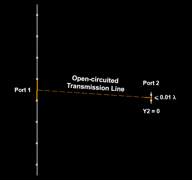
Due to the model used in the calculation engine, the transmission lines that are considered to exist in the simulation are those that have both ports connected to wire segments. Therefore, if you want to have an open-circuited line connected to a certain segment, the opposite port must also be connected to another wire segment. Create a short wire with only one segment that is no longer than 1% of the wavelength (its radius can be one-tenth of its length) and connect it to the open circuit transmission line port. This short wire should be disconnected from the rest of the structure, and the shunt admittance of the port it’s connected to should be zero, Fig. 1.

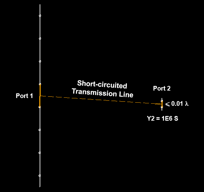
On the other hand, if you need a transmission line with a short-circuited port, connect that port to any other segment and set a shunt admittance at that end that is very large, for example, 1E6 [S]. At this end, you could connect a short wire segment created for this purpose, as is done for an open-circuited line, Fig. 2.

When creating short wires to connect open or short circuit transmission line ports, it is advisable to move these wires away from the rest of the structure to minimize interaction with it. Enter the length of the transmission line as indicated in Adding Transmission Lines. Remember that the length of the line is not necessarily related to the actual distance between the segments where it is connected.
