Search for answers or browse our Knowledge Base.
Guides | Models | Validation | Book
Efficient LEO and Weather Satellite Signal Reception with the Quadrifilar Helix Antenna
The Quadrifilar Helix antenna (QFH or QHA), through its specialized geometry, ensures robust reception for modern LEO satellite data links, providing high-quality imagery from polar-orbiting weather systems even at low elevation angles. This article explores the history, key characteristics, and practical modeling of QFH antennas using AN-SOF, providing valuable insights for RF engineers and enthusiasts.
Introduction
The Quadrifilar Helix (QFH) antenna, also known as the QHA, remains a premier choice for receiving signals from next-generation Low Earth Orbit (LEO) satellites, including the Meteor-M series and various environmental monitoring CubeSats.
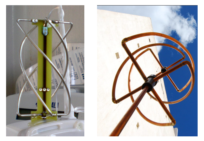
This intricate geometric arrangement (Fig. 1) provides unique properties optimized for modern satellite downlinks: a shaped hemispherical radiation pattern, excellent circular polarization purity to combat Faraday rotation, and self-resonance with a feedpoint impedance easily matched to standard 50 Ohm systems. While the QFH antenna’s bandwidth is narrower compared to a traveling-wave axial mode helix, its compact form factor makes up for this limitation.
Axial Mode Helical Antennas: History and Fundamentals
The axial mode helical antenna was invented in 1946 by John Kraus. Inspiration can come when we least expect it:
I attended an afternoon lecture on traveling-wave tubes by a famous scientist… In these tubes an electron beam is fired down the inside of a long wire helix for amplification of waves traveling along the helix. The helix is only a small fraction of a wavelength in diameter and acts as a guiding structure. … I asked the visitor if he thought a helix could be used as an antenna. ‘No,’ he replied, ‘I’ve tried it and it doesn’t work.’ The finality of his answer set me thinking. If the helix were larger in diameter than in a traveling-wave tube, I felt that it would have to radiate in some way, but how, I did not know. I determined to find out.
Dr. John D. Kraus, in “Antennas,” 2nd Ed. McGraw-Hill, 1988.
Today, helical antennas can be easily simulated (Fig. 2). Being wire antennas, the most efficient way to simulate them is through the Method of Moments (MoM). However, a poor convergence rate is often obtained for the input impedance when the helix is approximated by straight segments, as is customary. Using curved segments that exactly follow the helix contour overcomes this problem.
The axial mode helical antenna is one of the most widely used antennas for UHF and microwave communications. Its robust design makes it ideal for both space and ground applications, contributing significantly to the explosive growth of satellite-based services.

Traveling-Wave Antennas and Axial-Mode Helix:
Traveling-wave antennas are a class of antennas where the radio frequency (RF) energy travels along a structure, such as a wire, in a continuous wave. The axial mode helix is a specific type of traveling-wave antenna designed to operate in the axial mode. For a helix to operate in this mode, the circumference of the helix should be close to one wavelength of the operating frequency. Additionally, a metallic ground plane, often of circular shape, is added to the helix base, as shown in Fig. 2. These conditions allow the antenna to produce a directional radiation pattern with a main beam along the axis of the helix.
Circular Polarization:
The axial-mode helical antenna exhibits circular polarization, which can be either right-hand circular polarization (RHCP) or left-hand circular polarization (LHCP), depending on the winding sense of the helix. Circular polarization is achieved when the electric field of the wave rotates in a circular motion as it propagates. The sense of rotation, RHCP or LHCP, is determined by the direction in which the helix is wound. RHCP helical antennas are typically used for transmitting WEFAX pictures due to their reliable performance in space communications.
Importance of Circular Polarization:
Circular polarization is crucial in both space communications and terrestrial mobile applications. In space communications, circular polarization helps to mitigate the effects of Faraday rotation, an unpredictable phenomenon caused by the ionosphere, which can alter the polarization of the signal. By using circular polarization, satellite communications can maintain consistent signal quality despite these changes. In terrestrial mobile applications, circular polarization helps to reduce signal degradation caused by multipath interference, where signals bounce off various obstacles before reaching the receiver.
Key Characteristics of Quadrifilar Helical Antennas
The axial-mode helix antenna exhibits a consistent input impedance over a wide bandwidth, thanks to its nature as a traveling-wave antenna. For optimal performance, a ground plane with a diameter of about half to one wavelength is required. This antenna type can achieve a gain of 10-17 dBi over a 60% fractional bandwidth. However, with feedpoint impedances ranging from 150 to 300 Ohms, impedance matching is necessary for efficient operation in 50 Ohm systems.
By adding extra windings, the radiation pattern of the axial-mode helix can be tightened, and sidelobes can be reduced compared to a monofilar helix. The Quadrifilar Helix (QFH) antenna comprises four windings of equal torsion. Unlike long traveling-wave antennas, the QFH can be shortened to sizes commensurate with half a wavelength and operate as a resonant antenna, similar to a resonant dipole or loop antenna.
As a resonant antenna, the QFH has a narrow bandwidth, requiring careful attention to its dimensions and construction details. Its compactness and ease of integration with mobile systems make the short resonant QFH ideal for portable applications.
Each component helix of a QFH is excited in a 90-degree progression, either clockwise or counterclockwise, depending on the desired polarization and lobe direction. QFHs can operate in either endfire or backfire modes, producing a hemispherical directional pattern (Fig. 3). For long quadrifilar antennas, a quadrature feeding network is necessary to generate the 90° phase progressions. This can be achieved using quadrature hybrids and power splitters. For the small resonant helix, using two co-wound half helices with slightly different dimensions can induce quadrature excitation, similar to the “nearly square” method of generating circular polarization in a microstrip patch antenna.
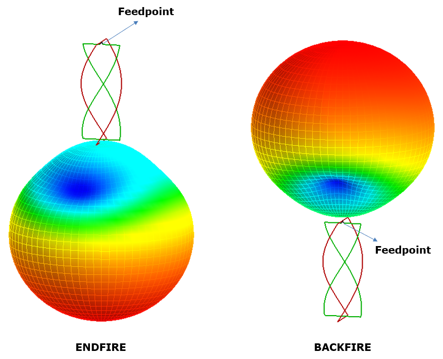
The feed phasing sense relative to the QFH winding sense determines the radiation mode: if they match, the antenna will be backfire; if they oppose, the antenna will be endfire. The circular polarization sense of the radiation is always opposite to the helix winding sense, regardless of the feed phasing sense. However, if a backfire helix antenna is used with a reflector or ground plane at the feed, the sense of the circular polarization is reversed, making the antenna endfire with the polarization sense corresponding to the helix winding.
Summary:
- The helix winding sense is opposed to the desired circular polarization sense. That is to say, left-hand wound helices in a QFH will generate right-hand circular polarization.
- Careful adjustment of the helix dimensions will produce a 50 Ohm feedpoint impedance without the need for external quadrature generating circuits or impedance matching networks.
- The backfire resonant quadrifilar helix antenna is popular for GNSS, communication, and weather satellite receiving stations. This antenna is configured for right-hand circular polarization, with a left-hand winding sense and the feedpoint at the top of the antenna.
- The QFH antenna’s ability to provide circular polarization and its compact form factor make it an essential tool for modern communication systems, ensuring reliable performance in a variety of challenging environments.
Input Parameters for Drawing a Helix in AN-SOF
AN-SOF allows you to draw helices quickly. Right-click on the workspace screen and choose Helix. There are two options for drawing a helix:
1. Start – Radius – Pitch – Turns: In this option, the helix is generated from a starting point along an axis with a defined pitch (distance between turns) and number of turns. The number of turns does not need to be an integer.
- When the pitch is positive, the helix is right-handed, running from the starting point along the +z axis, with the endpoint at z > 0.
- When the pitch is negative, the helix is left-handed, running along the -z axis, with the endpoint at z < 0.
Starting from AN-SOF version 9.50, you can enter the helix diameter, pitch angle, and filar length instead of the Radius-Pitch-Turns combination. The axial height is automatically calculated. The software warns when the wire diameter is greater than the pitch, preventing the overlapping of the windings.
2. Start – End – Radius – Turns: In this option, a helix with an integer number of turns connects the specified start and end points. The straight line connecting these points defines the axis of the helix. Only a helix with an integer number of turns can be mathematically defined between two given points, ensuring that the axis is parallel to the straight line joining them. The helix is right-handed if the number of turns is positive and left-handed if the number of turns is negative. Note that in this option, a pitch cannot be specified, as its value is determined by dividing the distance between the given start and end points (the axial height) by the number of turns (an integer).
A Scalable QFH Template for LEO Satellite Reception
The design depicted in Fig. 4 showcases an endfire QFH configuration originally optimized for the legacy NOAA 137 MHz weather satellite band.
The decommissioning and shutdown of the heritage NOAA POES transmitters in June and August 2025 marked the definitive conclusion of the 137 MHz analog weather imaging era. This transition signals a pivot toward more advanced, digital meteorological satellite systems. However, this specific model remains a high-performance template that can be scaled to any desired frequency range, from L-band (1.7 GHz) HRPT imaging to modern CubeSat downlinks in the S-band.
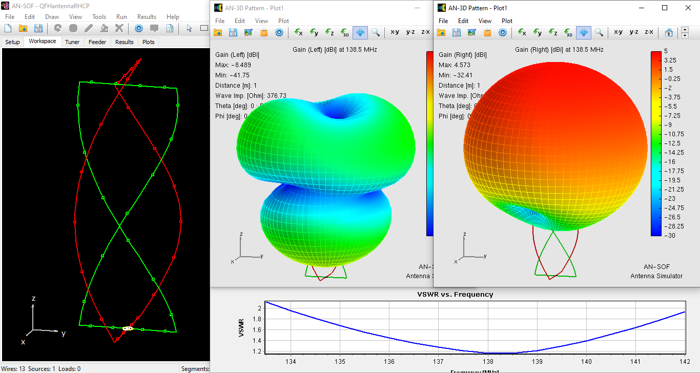
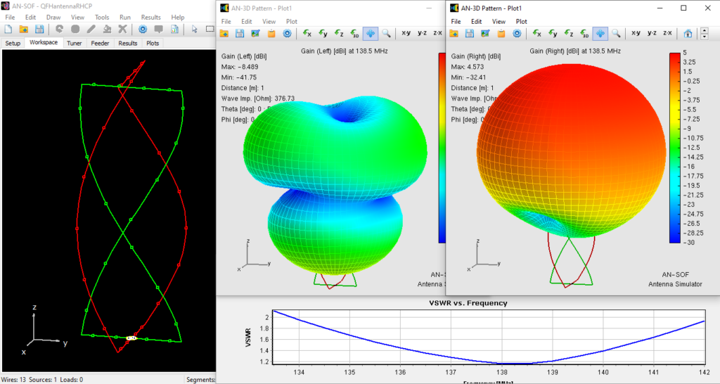
The geometry features a diameter of approximately $0.14\lambda$ (where $\lambda$ is the free-space wavelength) and helix lengths of $0.4\lambda$. In its original configuration, it exhibited a resonant frequency of 138.5 MHz and a fractional bandwidth of 6% (VSWR < 2). The helices composing the QFH antenna are left-handed, which, due to the phase relationship of the quadrifilar feed, results in a Right-Hand Circularly Polarized (RHCP) field. This is essential for modern satellite communications to effectively mitigate Faraday rotation and multipath interference.
In free space, the radiation pattern orients upward when the coaxial cable, simulated as a voltage source in the model, connects to the antenna’s bottom (endfire mode). The total gain is 4.6 dBi. AN-SOF allows for decomposing the gain into right-handed ($G_{RHCP}$) and left-handed ($G_{LHCP}$) polarizations. This demonstrates that the radiated field is purely RHCP, as the right-hand gain practically equals the total gain and the left-hand gain remains below -8.5 dBi. The resultant pattern is omnidirectional within the azimuth plane, which is invaluable for capturing signals across a wide variety of satellite pass geometries without the need for mechanical tracking.
Thanks to the implementation of the Conformal Method of Moments (CMoM) in AN-SOF, we can accurately model the behavior of the QFH with just 5 segments per helix. Because our wire segments are curved, they faithfully represent the contour of the helices with minimal segment counts, ensuring high computational efficiency. In summary, this QFH model stands as a robust, scalable configuration, offering a compact form factor, self-resonance, and high-purity RHCP for the next generation of satellite data acquisition.
Conclusions
The Quadrifilar Helix (QFH) antenna remains an exceptional choice for UHF and microwave communication, maintaining its status as a benchmark for satellite signal reception. While the legacy 137 MHz NOAA POES transmissions have concluded, the QFH design’s inherent circular polarization and compact form factor continue to ensure reliable performance across modern LEO constellations, such as the Meteor-M series, modern CubeSats, and advanced GNSS systems.
The historical evolution of the helical antenna underscores its versatility and enduring significance in the field of computational electromagnetics. By leveraging AN-SOF and its Conformal Method of Moments (CMoM) engine, researchers can efficiently scale, design, and optimize QFH antennas to achieve precise impedance matching and robust signal reception at any target frequency. This comprehensive framework equips engineers and enthusiasts with the mathematical tools necessary to adapt QFH geometries for next-generation communication needs, further cementing their role in the advancement of space-based data acquisition technologies.
See Also:
Technical Keywords: Quadrifilar Helix Antenna (QFH, QHA), LEO Satellite Communication, Circular Polarization (CP), Meteor-M Signal Reception, CubeSat Downlinks, AN-SOF Modeling, Next-Gen Weather Data, Conformal MoM, GNSS Systems, Impedance Matching.
