Search for answers or browse our Knowledge Base.
Guides | Models | Validation | Book
Energy Conservation and Gain Convergence in Cylindrical Dipoles: A Numerical Validation Study
Verify the numerical precision of the AN-SOF engine through this detailed validation study of cylindrical dipoles. By testing the principle of energy conservation, comparing input resistance against far-field radiation resistance, we demonstrate a near-perfect correlation with errors below 0.035%. This article also explores gain convergence, establishing that 10 segments per wavelength are sufficient to achieve high-precision results for linear antenna modeling.
The Principle of Energy Conservation
In the field of computational electromagnetics, the reliability of a numerical solver is fundamentally tied to its adherence to the laws of physics. One of the most stringent tests for any Method of Moments (MoM) engine is the verification of the energy conservation principle. In a lossless antenna system, an ideal environment with no ohmic or dielectric dissipation, the power supplied at the feed point ($P_{\text{in}}$) must be identical to the power radiated into the far-field ($P_{r}$).
This physical requirement allows for a unique validation check. By independently calculating the Input Resistance ($R_{\text{in}}$) from the voltage and current at the source and the Radiation Resistance ($R_{r}$) from the integration of the radiated power in the far-field, we can quantify the numerical precision of the solver. In an ideal PEC (Perfect Electric Conductor) model, any deviation between these two values is a direct measure of numerical artifacting rather than physical loss.
Simulation Model and Parameters
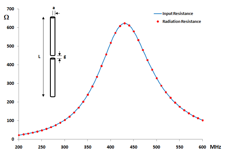
To conduct this validation, a center-fed cylindrical dipole was configured with the following parameters:
- Physical Length: $L = 0.5 \text{ m}$.
- Wire Radius: $a = 5 \text{ mm}$.
- Source Gap: $g = L/200$ ($2.5 \text{ mm}$).
- Frequency Range: $200 \text{ MHz}$ to $600 \text{ MHz}$.
- Environment: Free space (lossless).
This frequency sweep is chosen to observe the antenna’s behavior across multiple electrical lengths. At $300 \text{ MHz}$, the wavelength ($\lambda$) is approximately $1$ meter, making the $0.5 \text {m}$ dipole a half-wave radiator. At $600 \text{ MHz}$, the dipole reaches a full-wavelength ($L = \lambda$), where it enters a high-impedance anti-resonant state.
Comparative Analysis of the Dipole Input and Radiation Resistances
Figure 1 shows the input and radiation resistance as functions of frequency. The radiation resistance is derived by integrating the Poynting vector in the far-field to determine total radiated power and dividing the result by the square of the RMS current at the dipole center. In AN-SOF, the radiated power is available via the Power Budget window in the Results menu, while the input current can be retrieved through the List Currents command.
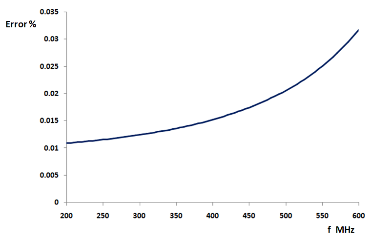
The results demonstrate a remarkable level of agreement. As seen in Figure 2, which tracks the percentage difference between these two quantities, the error remains consistently below 0.035% across the entire frequency range. This near-zero discrepancy confirms that the AN-SOF engine performs far-field power integration and near-field source calculations as a unified, energy-consistent system.
Gain Convergence and Discretization Guidelines
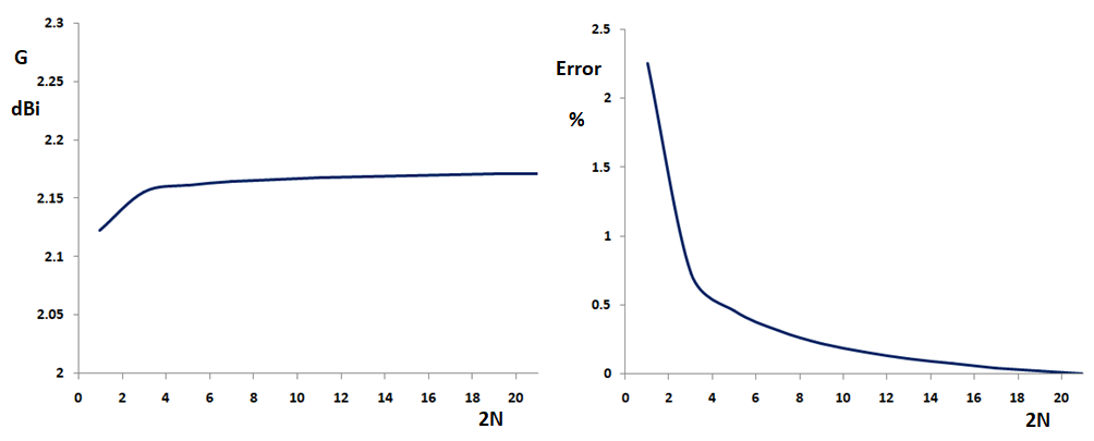
A second critical aspect of numerical validation is convergence. In MoM simulations, the accuracy of the results depends on the density of the wire segmentation. We investigated the convergence of the calculated peak gain ($G$) for a half-wave dipole as the number of segments ($2N$) increases, where $N$ represents the number of segments per dipole arm.
Figure 3 (left) shows that the gain values converge monotonically starting with as few as $2N = 3$ segments. To establish a practical baseline for engineers and designers, Figure 3 (right) highlights the error relative to the final asymptotic gain value. The data confirms that utilizing 5 segments per half-wavelength, equivalent to 10 segments per wavelength, results in a gain error of less than 0.5%. This validates the common “10 segments per $\lambda$” rule of thumb as a standard for linear antenna modeling to achieve accurate far-field metrics such as antenna gain.
Conclusion
The validation study of the center-fed cylindrical dipole demonstrates the exceptional numerical stability and precision of the AN-SOF solver. By achieving an energy conservation error of less than 0.035%, the software proves it can accurately handle the complex relationship between feed-point impedance and far-field radiation.
Furthermore, the convergence analysis provides a definitive benchmark for practitioners. The monotonic convergence of gain and the low error associated with standard segmentation densities ensure that users can obtain high-fidelity results with efficient computational overhead. Ultimately, these results provide the necessary confidence that AN-SOF’s treatment of linear antennas is grounded in strict physical conservation laws, making it a reliable tool for both resonant and harmonic antenna design.
See Also:
Technical Keywords: Cylindrical Dipole, Radiation Resistance, Input Resistance, Energy Conservation, Numerical Convergence, Gain Precision, Center-fed Antenna, AN-SOF Validation, Method of Moments, Segmentation Density.
