Search for answers or browse our Knowledge Base.
Guides | Models | Validation | Book
Introducing AN-SOF 10.5 – Smarter Tools, Faster Workflow, Greater Precision
We’re excited to announce the release of AN-SOF Antenna Simulator version 10.5, bringing a powerful set of new features and enhancements designed to improve your workflow and elevate your modeling precision.
Whether you’re an RF engineer, ham radio operator, or student of electromagnetics, this version is packed with improvements that make antenna design more intuitive, efficient, and insightful.
What’s New in AN-SOF 10.5?
✅ Iterate Faster with Enhanced Workflow
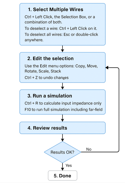
- Working with antenna elements has never been easier. Version 10.5 introduces enhanced wire selection tools—single or multiple wires can now be selected and remain selected across sessions, allowing you to resume work exactly where you left off.
- We’ve also added 10 levels of Undo/Redo, enabling you to iterate freely: select, edit, simulate, and refine—without fear of losing progress. Key editing tools like Move, Rotate, Scale, Copy, and Stack have been reimagined to support fast and flexible model building. This streamlines iterative modeling and simulation.
✅ Expanded Calculation Capabilities
- We’ve strengthened the simulation core with new options in the load impedance suite. You can now define Series, Parallel, and Trap RLC configurations, enabling accurate modeling of components such as traps and resonant circuits.
- The new Sommerfeld–Norton ground plane model enhances simulation accuracy at low heights, supporting horizontal wires as close as 0.005λ above ground. This capability is ideal for modeling linear or loop antennas situated near high-dielectric soils.
- Improved junction and stepped-radius algorithms also deliver up to 2× faster simulations, with no compromise in accuracy.
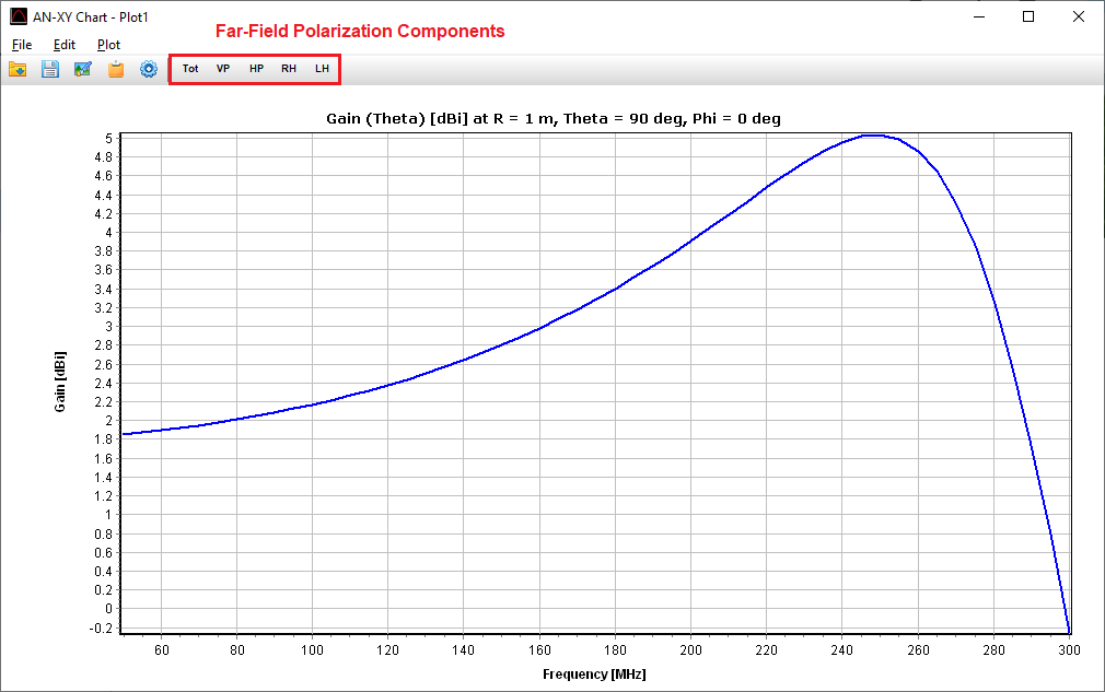
✅ Frequency-Dependent Far-Field Visualization
- Visualize performance across frequency with the new Far-Field Spectrum Plotting feature. Power Density, Gain, Directivity, and Radiation Patterns can now be plotted as functions of frequency in the AN-XY Chart.
- You can instantly display polarization components—VP, HP, RHCP, LHCP—with a single click for quick insight into your antenna’s behavior.
Explore the full list of updates and enhancements in the detailed release notes below, and see how AN-SOF 10.5 can help you work smarter and simulate better.
Happy antenna simulating!
Tony Golden
AN-SOF 10.5 Release Notes
💻 INTERFACE
Improvements in Wire Selection
- Refined Single & Multiple Selection: Enhancements have been made to single selection (
Right/Left Click,F8,F9,ESC) and multiple selection (Selection Box,Ctrl + Left Click). Selected wires remain visible and highlighted in light blue after transformations (Move, Rotate, Scale, Copy, Stack), ensuring seamless editing. When copying a wire or a group of wires, the wire color is now retained. - Persistent Selection: Wires remain selected until a double-click or
ESCis pressed, allowing users to perform multiple modifications consecutively and run simulations between changes without reselecting wires (watch the video and see the flowchart below). - Improved View Adjustments: Moving, rotating, and zooming the view now retains selected wires. The
ESCkey or double-clicking will unselect all wires. This refinement makes it easier to move, rotate, and zoom the view while selecting additional wires (Ctrl + Left Click) or deselecting them (Ctrl + Left Clickagain). - Selection Retention After Saving & Restart: Selected wires remain highlighted after saving the project and reopening AN-SOF, enabling immediate continuation of wire editing upon loading a project.
- Integration with Bottom Toolbar: Users can now move, rotate, and zoom the view while the Add Source/Load/TL toolbar or List Currents toolbar is open. This makes it easier to add sources, loads, connect transmission lines, or view impedance, current, voltage, and power data at selected wire segments. The toolbar can remain open while selecting new wires.
New Undo/Redo Functionality
- Multi-Level Undo/Redo: The new Undo (
Ctrl + Z) and Redo (Ctrl + Y) options, accessible via the Edit menu and main toolbar, now support 10 levels of undo/redo—a major improvement over the previous single-level undo.
Improved Zoom Behavior
- Zooming now centers around wire positions rather than the coordinate origin, ensuring a smoother workflow when adjusting views.
- When a ground plane is present, the zoom remains focused on relevant elements.
- Zooming can be controlled using the mouse wheel for greater convenience.
Persistent Axes Display
- After pressing the “Home” button on the toolbar, the main axes remain visible if they were previously displayed.
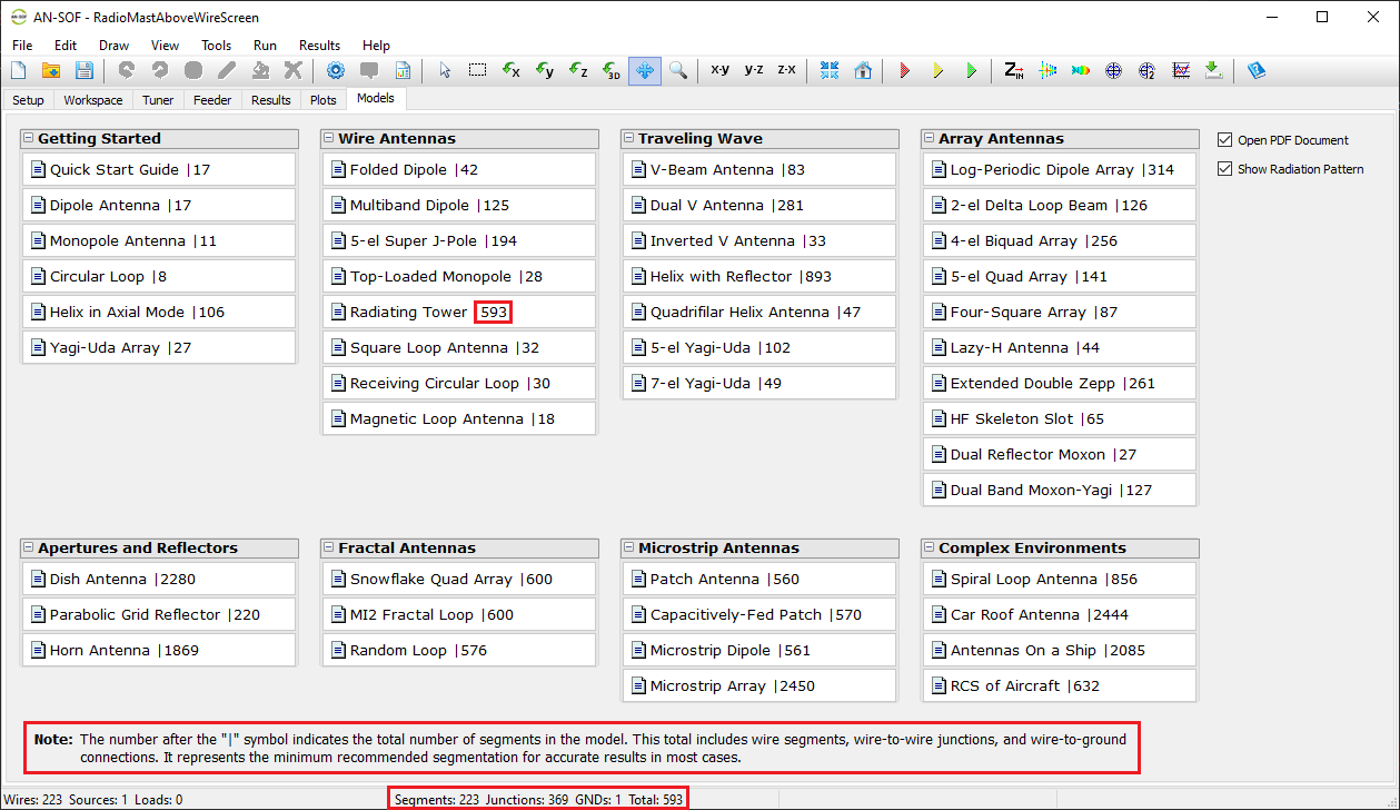
Segment Count Display
- The total number of segments per model is now shown:
- After the “|” symbol on each button label in the Models tab.
- In the Status Bar at the bottom of the AN-SOF window.
- This total includes:
- Wire segments
- Wire-to-wire junctions
- Wire-to-ground connections (labeled as “GNDs”)
New Exportation of Script Templates
- Effortless Script Exportation for Scilab & Octave: Users can now export script templates from Main Menu > File > Export Wires:
- “.sce” files → Ready for Scilab scripting
- “.m” files → Compatible with Octave
- Automated Sweeps & Optimizations: These scripts enable the development of sweepers (automating multiple simulations with varying antenna geometric parameters) and optimizers (modifying antenna input files dynamically via an optimization script in combination with the AN-SOF Engine to minimize, maximize, or achieve target performance metrics).
🧮 CALCULATIONS
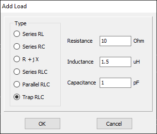
New Load Impedance Types
- The suite of lumped load impedances has been expanded beyond Series RL, RC, and R + jX to include Series, Parallel, and Trap RLC configurations. A Trap load consists of a series RL combined with a parallel C, making it highly useful for modeling inductors, traps, or other parallel resonant circuits.
- Load Importation & Exportation in .NEC Files: Loads can now be imported and exported using specific commands:
- LD 0 → Series RL, RC, or RLC
- LD 1 → Parallel RLC
- LD 4 → Fixed impedance (R + jX)
- LD 5 → Wire conductivity addition
- NEW! LD 6 → Trap RLC load
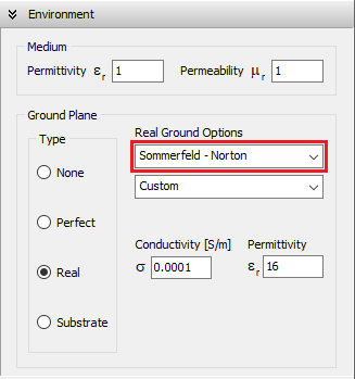
New Sommerfeld–Norton Ground Plane Model
- A new Sommerfeld–Norton ground plane model has been implemented, allowing accurate calculations for:
- Horizontal wires, including loops and linear wires, down to 0.005λ above ground.
- Vertical wires raised by approximately one wire radius above ground.
- Wire-to-ground connections are supported, though their interactions are modeled via specular reflection, so the ground must be a good conductor at the selected frequency. For wires connected to poorly conductive grounds, it’s recommended to use the Sommerfeld–Wait Asymptotic model instead.
- The Sommerfeld–Norton model is particularly suitable for dielectric grounds with no direct wire connections.
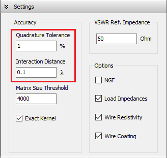
Enhanced Wire Junction and Stepped Radius Calculations
A new technique has been implemented to solve singular integrals that occur when a wire junction undergoes a radius change. This significantly improves junction calculations, eliminating the need to retain the default conservative parameters in the Settings panel:
- Previous defaults: Quadrature Tolerance = 0.1%, Interaction Distance = 1 λ
- New recommended defaults: Quadrature Tolerance = 1%, Interaction Distance = 0.1 λ
These optimized settings improve calculation speed by up to 2× while maintaining—or even improving—accuracy. When recalculating a model, you may notice minimal differences in the third or fourth decimal place, or occasionally larger differences, but the new method provides greater precision. All example models in the Examples folder provided with the AN-SOF installation files have been updated accordingly.
Refined Toolbar Buttons & Commands in the Run Menu
To streamline the simulation process, some commands have been adjusted:
- Run Currents and Far Field → (F10)
- Run Currents and Near Field → (F11)
- Run ALL → (F12)
Many users who are not interested in near-field calculations were previously selecting Run ALL, unintentionally increasing computation time. These changes help avoid unnecessary near-field calculations.
📈 RESULTS
New Far-Field Spectrum Plotting
Power Density, Directivity, Gain, and Radiation Pattern can now be plotted as a function of frequency in the AN-XY Chart:
- Navigate to Main Menu > Results > Plot Far-Field Spectrum
- Select polarization components via toolbar buttons:
- VP (Vertically Polarized)
- HP (Horizontally Polarized)
- RH (Right-Hand Circularly Polarized)
- LH (Left-Hand Circularly Polarized)