Search for answers or browse our Knowledge Base.
Guides | Models | Validation | Book
Design and Analysis of a Parabolic Cylinder Reflector with a Back-Firing Primary Radiator
Explore the design of a self-resonant parabolic cylinder reflector antenna operating at 890-965 MHz. This study analyzes a back-firing dipole-reflector feed system modeled in AN-SOF, demonstrating how to achieve a stable 50-Ohm match and an asymmetric fan-beam pattern (55° Horizontal, 25° Vertical) without complex matching networks.
Introduction to Parabolic Cylinder Theory
While the standard paraboloid of revolution focuses energy into a single point, the parabolic cylinder reflector focuses a plane wave onto a focal line. This geometry is defined by the parabolic equation in a single plane (usually $x^2 = 4fy$ in the $xy$-plane, $f$ being the focal length), extended linearly along the perpendicular axis.
The primary advantage of this configuration is the independent control it offers over the horizontal and vertical beamwidths. By adjusting the height and width of the cylinder separately, we can create a “fan beam,” narrow in one plane and broad in the other, which is exactly what we observe in this 890-965 MHz model.
Primary Radiator: The Back-Firing Dipole-Reflector Assembly
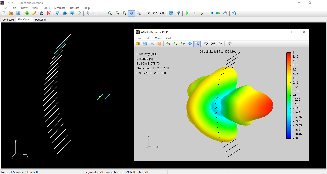
In this AN-SOF model, the primary radiator is positioned at the focal line. It consists of a dipole-reflector assembly designed for back-firing operation. The driven element is a half-wave dipole, and the parasitic reflector is slightly longer to ensure that the bulk of the radiated energy is directed toward the parabolic surface rather than away from it.
As seen in Fig. 1, the entire assembly is modeled within the AN-SOF workspace. This configuration ensures that the parabolic cylinder is illuminated with a specific phase front, maximizing the efficiency of the aperture.
Geometric and Electromagnetic Modeling
The reflector dimensions are scaled to the center frequency of 927 MHz ($\lambda \approx 0.32\text{ m}$):
- Aperture Width: $1.15\lambda$
- Aperture Height ($D$): $2.3\lambda$
- Focal Length ($f$): $1.06\lambda$
Because the antenna uses linear polarization parallel to the elements, the parabolic surface is modeled using discrete linear wires. If the wire spacing is sufficiently smaller than $\lambda/10$, the grid approaches a perfect electrical conductor (PEC) for the co-polarized field.
Simulation Results & Performance Metrics
One of the most important aspects of this design is that it is self-resonant. Many reflector feeds require complex matching networks (stubs or transformers) to reach a $50\,\Omega$ characteristic impedance. Here, the mutual coupling between the dipole, its parasitic reflector, and the parabolic cylinder has been balanced to provide a natural match.
Analysis of the Results:
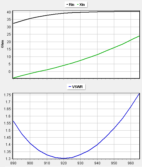
- Impedance and VSWR: As illustrated in Fig. 2, the VSWR remains below 1.75 across the 890-965 MHz band. The input impedance sits close to the $50\,\Omega$ center point, eliminating the need for external tuning.
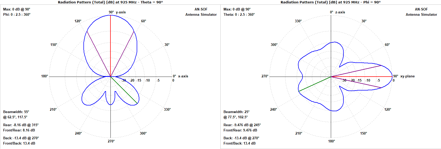
- Radiation Patterns: The antenna exhibits a clear fan-beam characteristic. The Horizontal Beamwidth (HPBW) is $55^\circ$, while the Vertical Beamwidth is $25^\circ$ (Fig. 3). This asymmetry is a direct result of the $2:1$ height-to-width ratio of the parabolic cylinder. The average Front-to-Back ratio (F/B) is 13 dB.
- Gain and Directivity: The gain varies from 12 to 10 dBi across the band. The frequency dependence of the radiation pattern in decibels can be seen in the animation in Fig. 4.
R+D+I: Opportunities for Optimization
While this model provides an excellent baseline, further optimization could enhance the gain. Currently, the $f/D$ ratio (focal length to aperture height) is approximately 0.46. Reducing the focal length and increasing the aperture size could improve the illumination efficiency and increase the gain. However, any change in the $f/D$ ratio will alter the mutual coupling between the feed and the reflector, potentially shifting the resonance. Future iterations could use the Nelder-Mead optimization script and the AN-SOF Engine to find the “sweet spot” where gain is maximized while maintaining the current self-resonant $50\,\Omega$ match.
Conclusions
The AN-SOF simulation of the parabolic cylinder reflector demonstrates a high-performance, self-resonant design suitable for targeted 900 MHz applications. By integrating a back-firing feed, we achieved a stable $50\, \Omega$ match without external tuning components.
However, R+D+I opportunities remain. The current $f/D$ ratio and aperture size are optimized for resonance, but there is headroom to increase the peak gain. Future iterations will focus on optimizing the focal length-to-aperture ratio. By employing the Nelder-Mead optimization script and the AN-SOF Engine, we can refine the surface illumination to suppress spillover and sharpen the beamwidths, further enhancing the 12 dBi gain while maintaining the inherent self-resonant properties of the structure.
See Also:
- High-Gain Biquad Antenna with Planar Reflector: Analysis and Applications for the 866.5 MHz ISM Band
Technical Keywords: Parabolic Cylinder, Back-Firing Feed, Self-Resonant Antenna, Fan Beam, Focal Line, 927 MHz, AN-SOF Simulation.
