Search for answers or browse our Knowledge Base.
Guides | Models | Validation | Book
High-Performance Impedance Matching in Microstrip Antennas: The Role of Capacitive Feeding
Overcome probe inductance and simplify your antenna designs with capacitive feeding. This study demonstrates how to utilize proximity coupling to achieve a perfect 50-Ohm match and 10 dBi gain. Validated against classic experimental benchmarks, our simulation shows how internal reactance cancellation enables wideband performance in microstrip patches without external matching networks.
The Evolution of Microstrip Feeding Techniques
Microstrip patch antennas are ubiquitous in modern wireless communication due to their low profile and ease of integration. However, as applications demand wider bandwidths, designers typically increase the substrate thickness. This physical change introduces a significant electromagnetic penalty: the coaxial feed probe becomes electrically long, introducing an unwanted inductive reactance. This parasitic inductance shifts the resonance and degrades the Voltage Standing Wave Ratio (VSWR), traditionally necessitating external impedance-matching networks that increase complexity and footprint.
The capacitive feeding method represents a sophisticated solution to this challenge. By decoupling the physical connection between the probe and the radiating element, and instead utilizing proximity coupling through a small intermediate patch, the inherent inductance of the feed can be neutralized internally.
Understanding the Physics of Capacitive Cancellation
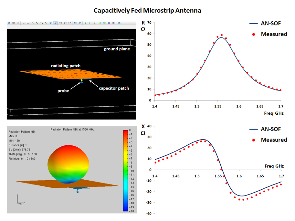
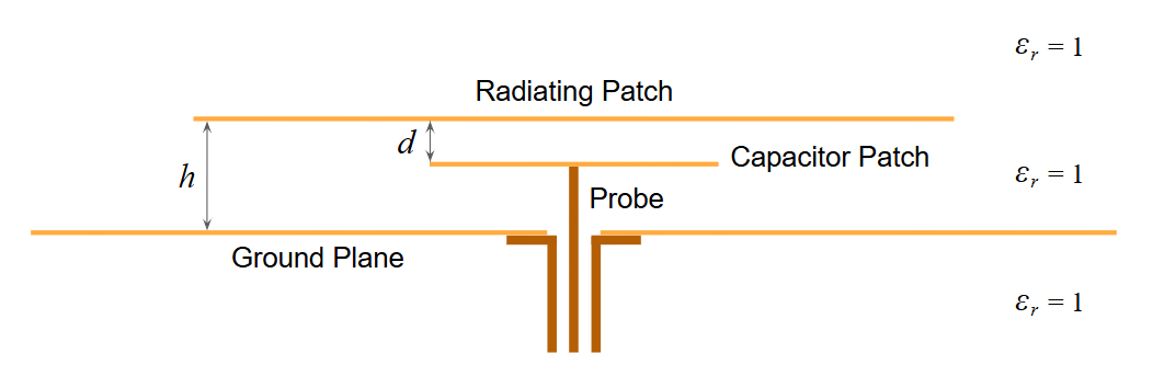
In a capacitively fed architecture, the coaxial probe terminates at a small “capacitor patch” situated between the ground plane and the main radiating element (Fig. 1). This configuration creates a series capacitance that acts as a compensator. From a circuit perspective, the inductive reactance of the feed probe is canceled by the negative reactance of the capacitive gap.
The primary advantage of this approach is the ability to achieve a perfect 50-Ohm match at the desired frequency simply by adjusting the geometry of the coupling patches, rather than relying on external stubs or transformers. This has been a critical breakthrough for the development of Planar Inverted-F Antennas (PIFAs) and other compact radiators used extensively in the mobile phone industry.
Geometric Configuration and Model Setup
To demonstrate the precision of this technique, a suspended patch model was analyzed using the AN-SOF simulation engine (Fig. 2). Modeling the structure in air ($\epsilon_r = 1$) allows for a pure examination of the coupling dynamics without the influence of substrate losses or dielectric uncertainty.
Detailed Model Dimensions:
- Radiating Element: A square PEC patch measuring $82.5 \times 82.5\text{ mm}$.
- Capacitor Patch: A square PEC patch measuring $20 \times 20\text{ mm}$.
- Ground Plane: A large square PEC surface of $600 \times 600\text{ mm}$ (approx. $3\lambda$ at the center frequency).
- Vertical Stacking: The radiating patch is positioned $h = 6.85\text{ mm}$ above the ground plane. The capacitor patch is suspended $d = 2.25\text{ mm}$ below the radiating patch.
- Feed Offset: To achieve the required resistance, the capacitor patch is offset $22\text{ mm}$ from the center of the radiating patch.
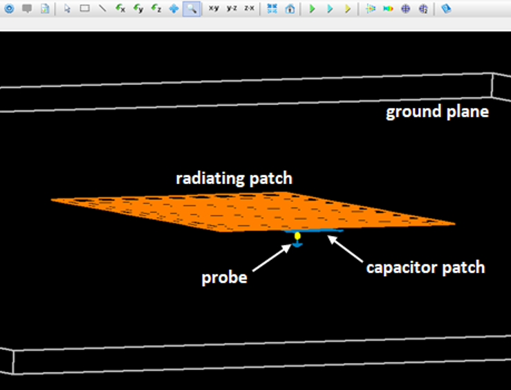
The model shown in Fig. 2 was constructed by defining a Patch with $10 \times 10$ facets for the radiating patch and a wire grid representing a solid surface with $5 \times 5$ facets for the capacitor patch. A finite PEC ground plane was set under the Substrate option in the Environment panel. The model can be downloaded via the button below the figure.
Input Impedance and Resonance Analysis
To verify the predictive capabilities of the AN-SOF engine, the antenna geometry and experimental results for this study were sourced from the paper by G.A.E. Vandenbosch and A.R. Van de Capelle, “Study of the Capacitively Fed Microstrip Antenna Element” (IEEE Trans. Ant. Propag., vol. 42, no. 12, 1994). This publication serves as a primary benchmark in the field of computational electromagnetics, providing a rigorous set of measured data for suspended microstrip patches. By utilizing these specific dimensions and empirical results, this simulation acts as a formal validation of the software’s ability to model proximity-coupled structures with high precision.
The simulation was conducted across a frequency sweep from 1.4 to 1.7 GHz. The resulting input impedance data reveals the classic signature of a high-performance resonant structure (Fig. 3).
The real part of the input impedance follows a bell-shaped curve, reaching a peak of approximately 60 Ohms at 1.56 GHz. Simultaneously, the input reactance exhibits a parallel resonant transition, crossing the zero-Ohm axis at 1.56 GHz. This alignment confirms that the capacitive feed has successfully tuned the antenna to a purely resistive state at its primary resonance.
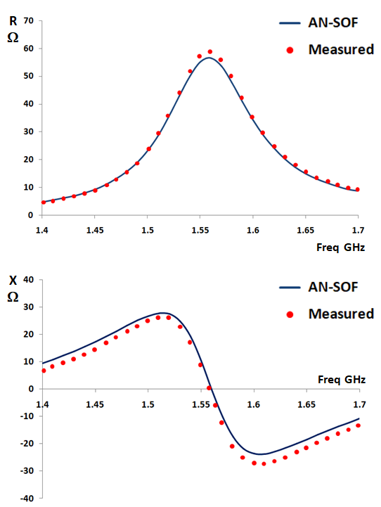
The bandwidth performance is equally impressive. For a 2:1 VSWR relative to a 50-Ohm system, the antenna achieves a 5% fractional bandwidth. This capability to maintain a stable match over a significant range is a direct result of the optimized proximity coupling.
Validation Against Empirical Data
A critical aspect of this study is the comparison between AN-SOF numerical results and established experimental measurements for this specific geometry.
Numerical results show that the calculated real and imaginary parts of the input impedance are nearly coincident with measured data reported by G.A.E. Vandenbosch and A.R. Van de Capelle, as shown in Fig. 3. Specifically, the resonance frequency of 1.56 GHz matches the empirical benchmark with negligible error. Notably, the AN-SOF implementation provides a higher degree of correlation to the measured curves than the original theoretical calculations proposed in early literature. This precision underscores the effectiveness of the Conformal Method of Moments (CMoM) in capturing the complex near-field interactions between overlapping metallic layers.
Radiation Patterns and Gain Efficiency
The electromagnetic performance extends beyond impedance matching to highly efficient radiation characteristics. Throughout the 1.4 to 1.7 GHz band, the gain remains stable between 9 and 10 dBi.
The radiation pattern is characterized by a clean, broadside main lobe directed perpendicularly away from the ground plane (Fig. 4). No significant side lobes or grating lobes are observed, indicating a well-behaved current distribution on the radiating patch.
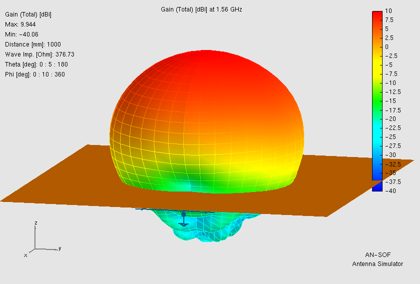
The impact of the ground plane size is evident in the Front-to-Back (F/B) ratio. Although some diffraction occurs at the edges of the 600 mm ground plane, the energy leaked into the back hemisphere is suppressed to approximately -30 dB relative to the peak gain. This high degree of isolation is ideal for applications requiring unidirectional coverage and minimal interference with electronics located behind the antenna.
Conclusion
The study of capacitively fed microstrip elements confirms that proximity coupling is an exceptionally effective method for managing feed probe reactance. By integrating a capacitor patch into the antenna’s internal architecture, designers can achieve wideband performance and a stable 50-Ohm match without the need for external tuning components. The perfect agreement between simulation and measurement validates this model as a benchmark for engineers designing advanced, compact radiators for the next generation of wireless devices.
See Also:
Technical Keywords: Microstrip Patch Antenna, Capacitive Feeding, Impedance Matching, Probe Reactance Cancellation, Resonant Resistance, AN-SOF Simulation, PIFA Design.
