Search for answers or browse our Knowledge Base.
Guides | Models | Validation | Book
Introduction to Yagi-Uda Arrays: Analyzing a 5-Element Beam with a Folded Dipole Driver
Learn the fundamentals of Yagi-Uda arrays with this introductory model. This simulation features a folded dipole driver with arced ends, illustrating how parasitic elements shape a highly directional 9.7 dBi beam and achieve a 15 dB Front-to-Back ratio. This baseline design provides the perfect foundation for mastering antenna feeding, tuning, and optimization using AN-SOF.
The Fundamentals of Parasitic Arrays
The Yagi-Uda antenna is the quintessential directional beam antenna. By placing “parasitic” (unfed) elements in the near field of a “driven” element, we can shape the radiation pattern through mutual coupling. In this introductory model, we explore a 5-element configuration at 100 MHz, consisting of one reflector, one driven element, and three directors (Fig. 1).
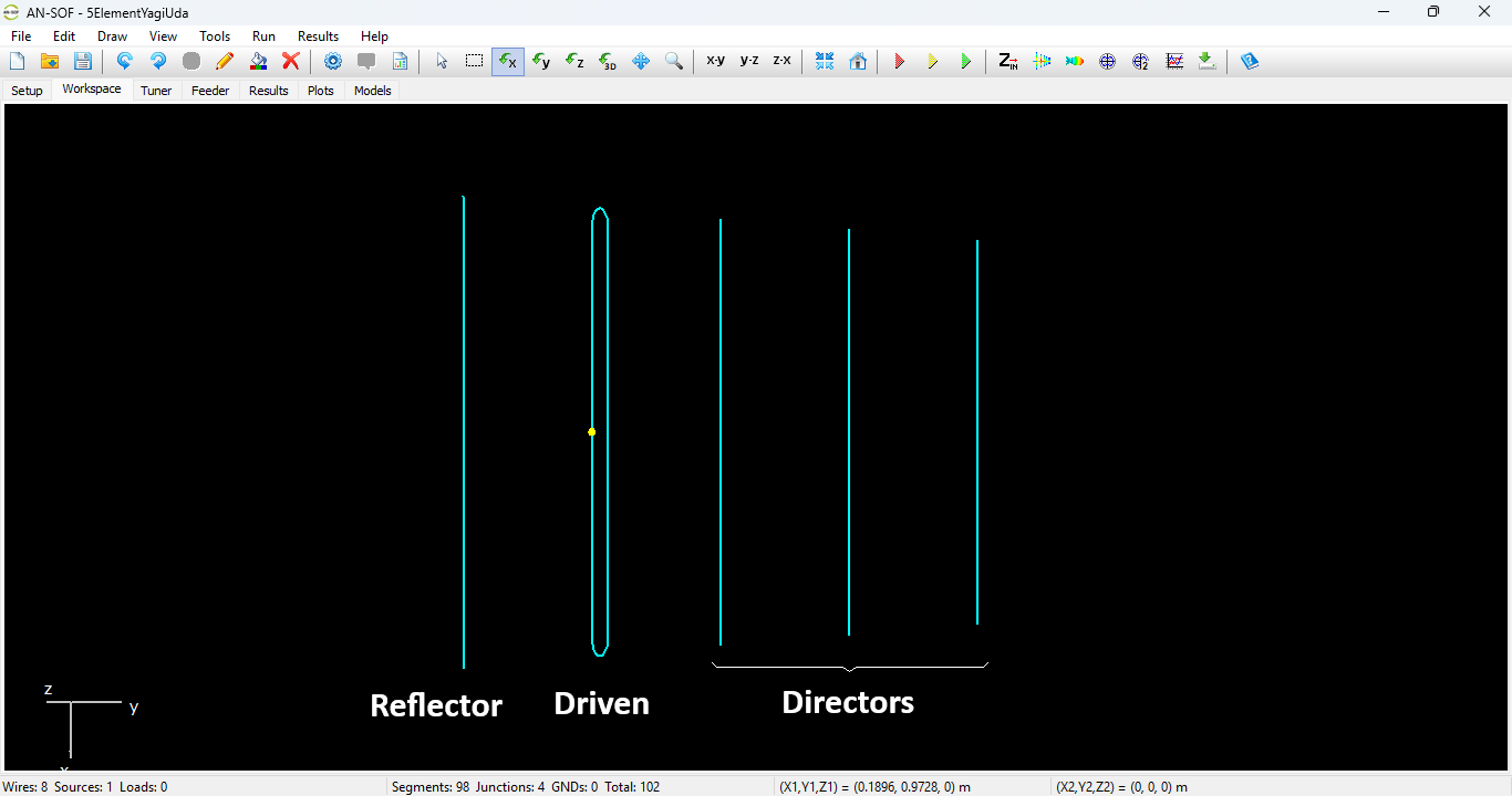
Geometric Modeling in AN-SOF
One unique feature of this model is the driven element: a folded dipole with arced wire ends. Unlike a standard dipole, the folded configuration provides a natural impedance step-up and increased bandwidth.
By using AN-SOF’s Conformal Method of Moments (CMoM), the arced ends of the folded dipole are modeled with exact geometric curvature. This ensures high numerical precision in the calculation of the surface currents where the wire bends, a critical area for determining the final input impedance.
Model Dimensions (at 100 MHz):
- Reflector: $1.5\text{ m}$
- Driven Element (Folded): $1.425\text{ m}$ (Length) x $0.12\text{ m}$ (Width)
- 1st Director: $1.354\text{ m}$
- 2nd Director: $1.286\text{ m}$
- 3rd Director: $1.222\text{ m}$
- Element Spacing: A constant $0.45\text{ m}$ between all adjacent elements.
This article offers a step-by-step tutorial for constructing a Yagi-Uda antenna within the AN-SOF workspace:
Why use a Folded Dipole?
In a Yagi-Uda array, the proximity of parasitic elements typically causes the radiation resistance of the driven element to drop significantly, often well below $50\, \Omega$. By using a folded dipole, which has a self-impedance approximately four times that of a standard dipole, we can keep the final impedance in a range that is easier to match to standard transmission lines.
Simulation Results
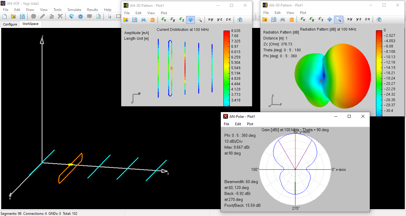
Even without specific optimization, this 5-element array demonstrates the powerful directional characteristics of the Yagi-Uda design:
- Forward Gain: $9.7\text{ dBi}$
- Front-to-Back (F/B) Ratio: $15\text{ dB}$
- Input Impedance: $162 + j121\; \Omega$
Figure 2 presents a complete electromagnetic profile of the 5-element Yagi-Uda array. Note the symmetry in the current distribution and the significant forward directivity, which is achieved through the precise interaction of the parasitic elements as modeled in AN-SOF.
The complex impedance ($+j121\, \Omega$) indicates that the antenna is currently inductive and not yet resonant at the design frequency. This provides a perfect starting point for users to learn the art of antenna “tuning.”
Next Steps: Feeding, Tuning, and Optimization
This model serves as a baseline. To transform this into a production-ready antenna, two distinct engineering steps are required:
- Feeding and Tuning: To eliminate the reactive component ($jX$) and match the antenna to your feedline, refer to our comprehensive guide: “Complete Workflow: Modeling, Feeding, and Tuning a 20m Band Dipole Antenna”.
- Optimization: The gain and F/B ratio can be significantly enhanced by varying the lengths and spacings of the directors. Advanced users can automate this process using our specialized scripts and methods:
See Also:
Technical Keywords: Yagi-Uda Array, Folded Dipole, Parasitic Elements, Conformal MoM, Antenna Gain, Front-to-Back Ratio, 100 MHz Beam.
