Search for answers or browse our Knowledge Base.
Guides | Models | Validation | Blog
Exploring the Spiral Loop Antenna: A Compact Solution for 80m DXing
Uncover the compact marvel of the Spiral Loop Antenna, offering a unique solution for 80m DXing enthusiasts seeking efficient performance in limited space.
Key Takeaways
- Space-Saving Alternative: Spiral loops offer a compact solution, addressing the space constraints of traditional dipoles.
- Tackling Efficiency Challenges: Despite efficiency hurdles, spiral loops provide easy tuning and a respectable bandwidth.
- AN-SOF’s Precision: AN-SOF enables accurate spiral loop modeling, empowering hams to innovate designs for diverse conditions.
A half-wave dipole for the 80 meters band (3.75 MHz) would require a length of 40 meters, making it difficult to install at home due to space constraints and potential neighbor complaints.
In contrast, a spiral loop offers a compact size and relative ease of tuning. Essentially an inductor with a variable capacitor connected at the feed point to achieve resonance, it provides an attractive alternative. However, its radiation resistance is extremely small, typically on the order of milliohms, resulting in low efficiency.
Unfortunately, any small loss can significantly impact the antenna’s efficiency, including losses in the capacitor, wires, interconnections, solder joints, surrounding objects, and ground plane. Despite these challenges, the antenna can be tuned to achieve a wide bandwidth, albeit with reduced efficiency. Maximum radiation occurs vertically when the antenna is installed perpendicular to the ground plane, although some suggest horizontal installation to mitigate potential high voltages across the tuning capacitor.
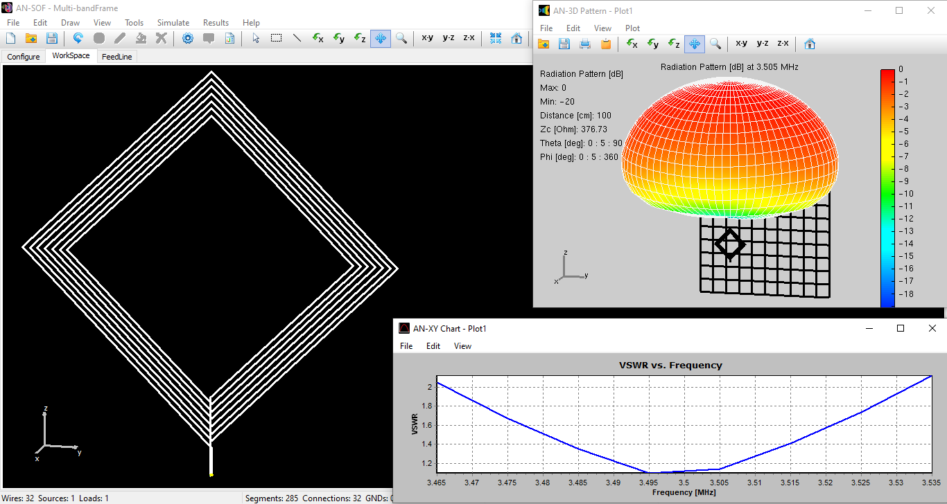
The AN-SOF model depicted in the figure below consists of a 50 cm frame on each side, corresponding to 0.00625 of the wavelength (λ = 80 m), with 7 turns of wire. Simulating closely spaced and bent wire segments, as depicted, is crucial for accurate representation.
The following input resistance results demonstrate the impact of incorporating losses in the ground plane and adding surrounding objects, such as a wall:
- Perfect ground: 4 milliohms
- “Cities industrial poor” ground: 1.3 Ohms
- “Cities industrial poor” ground + wall: 49 Ohms
The figure above depicts the 3D radiation pattern of the spiral loop antenna in the presence of a wall and a ground plane with “Cities industrial poor” characteristics (conductivity σ = 0.0001 S/m and relative permittivity εr = 3). The lower vertex of the antenna frame is elevated 1.5 m above the ground. The wall, measuring 3 m x 3 m, is positioned 3 m away from the antenna and is modeled by a 10 x 10 wire grid. In this scenario, the radiation pattern points upward, although it is omnidirectional in the horizontal plane. Additionally, the figure shows the VSWR as a function of frequency, with a bandwidth for VSWR = 2 of about 70 KHz, representing 2% of the center frequency of 3.5 MHz.
This design can be easily adapted into a multi-band antenna by shorting turns of wire, similar to adjusting a variable inductor, enabling operation on the 40, 30, and 20 meter bands.
In conclusion, AN-SOF’s capability to accurately model antennas with closely spaced and bent wires proves invaluable in analyzing complex designs like the spiral loop antenna. By simulating intricate geometries and accounting for factors such as surrounding objects and ground losses, AN-SOF empowers radio hams to optimize antenna performance and adapt designs for diverse operating conditions with confidence.