Search for answers or browse our Knowledge Base.
Guides | Models | Validation | Book
AN-SOF Engine User Guide
Master antenna modeling with the AN-SOF Engine—a high-performance simulation tool for advanced users. Configure input files, analyze results, and troubleshoot designs. Supports linear wires, helices, and arcs with RAM-optimized precision.
Introduction to the AN-SOF Engine
What is the AN-SOF Engine?
This guide explains how to operate the AN-SOF Engine, assuming the user is already familiar with AN-SOF—our simulation software for antenna modeling and design. Prior experience with AN-SOF is essential for understanding this guide. If you are new to AN-SOF, we recommend starting with the User Guide and exploring the model examples in our Knowledge Base.
AN-SOF comprises two main components:
- A user interface (UI) for interaction and visualization.
- A calculation engine, which is a sophisticated software system implementing numerical algorithms for the Conformal Method of Moments (CMoM).
The CMoM is unique to AN-SOF and offers significant advantages over traditional Moment Method implementations. The AN-SOF Engine serves as the computational core of the software.
In the standard versions of AN-SOF (which bundle the UI and engine), the engine is optimized to use Windows onboard memory, typically limited to 2 GB. This constraint restricts the maximum number of wire segments to approximately 7,000, accounting for:
- Wire subdivisions,
- Junctions (which require additional segments),
- Ground connections.
This capacity is sufficient for modeling most wire-based antenna projects, including:
- Wire antennas (dipoles, loops, etc.),
- Traveling-wave antennas (Yagis, helices),
- Wire-based arrays,
- Fractal structures,
- Microstrip-supported designs (within the engine’s capabilities).
However, aperture and reflector antennas (e.g., horns, parabolic dishes) often demand higher segment counts, exceeding onboard memory limits. To address this, we extracted AN-SOF’s core algorithms and developed a standalone engine that leverages system RAM, enabling larger and more complex simulations.
Capabilities of the AN-SOF Engine
The AN-SOF Engine is a console-based application with no graphical user interface (UI). This design serves three key purposes:
- Extending Segment Limits to Available RAM
- Removes the 10-square-wavelength restriction for modeling solid metallic surfaces.
- Enables simulation of electrically larger structures, such as:
- Horn antennas
- Parabolic reflectors
- Other aperture antennas.
- Faster Calculations Without Sacrificing Accuracy
- Runs computations up to 3× faster than the standard AN-SOF engine.
- Enhances precision in far-field metrics, including:
- Directivity
- Gain
- Radiation efficiency.
- Retains the high accuracy of AN-SOF’s exclusive Conformal Method of Moments (CMoM).
- Programmable Integration for Advanced Control
- Designed as a console application for seamless integration with third-party tools.
- Enables:
- Automated batch processing (e.g., parametric sweeps).
- Custom optimization workflows (compatible with established optimization algorithms).
- Deep-level control for users with programming expertise.
Note:
The AN-SOF Engine currently supports up to 63,000 wire segments, including wire-to-wire junctions and wire-to-ground connections. A project of this size requires approximately 64 GB of available RAM, based on the estimation that memory usage grows as 16 × N² bytes, where N is the number of segments. For large aperture antennas, please consult our Tech Support Team to assess whether your project can be run using the AN-SOF Engine.
Why Use the AN-SOF Engine?
If you need an advanced, high-performance antenna simulation tool that offers:
- Scalability (beyond onboard memory limits),
- Speed (3× faster calculations),
- Precision (improved far-field accuracy),
- Flexibility (scriptable and optimizable),
—then you’re in the right place. Welcome to the AN-SOF Engine User Guide!
Download, Installation, and Activation
License Requirements
The AN-SOF Engine is available to customers with a Platinum plan. Review the features of this plan on our Pricing page.
- Trial Version:
- Limited to 50 segments (including connections).
- Enabled by default—no activation required.
- PRO Version:
- Removes segment limitations.
- Requires a Platinum plan subscription and an activation key.
- Includes:
- Activation on 2 PCs.
- 1 year of updates and technical support.
Installation Instructions
The AN-SOF Engine is distributed as raw files (no installer). Follow these steps:
- 📥 Download
- Click the button below to download the
.zippackage:
- Click the button below to download the
- 📂 Extract Files
- Unzip the downloaded file.
- Save the contents to a dedicated folder (e.g.,
C:\AN-SOF Engine). - ⚠️ Avoid system directories like
Program Filesto prevent permission issues.
- 🛠️ Run the Engine
- Locate
AN-SOFengine.exe(the main executable). - If launched now, it will display an error (input file path not configured).
- Locate
Antivirus Considerations
AN-SOF files are virus-free, but Windows Defender/antivirus software may flag them. If blocked:
- Click “More Info” → “Run Anyway” (see the image below).
- If issues persist, right-click
AN-SOFengine.exe→ “Run as administrator”. - After the first run, Windows will recognize the engine as trusted.

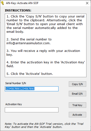
Activation Process
To activate your PRO license:
- Locate
an_key_engine.exe(in the same folder asAN-SOFengine.exe). - Follow the on-screen instructions to (see the image below):
- Submit your serial number.
- Request an activation key 🔑.
Configuring the Input File Path
The AN-SOF Engine requires an input file in NEC format, containing commands supported by AN-SOF (see Importing Wires). To specify the input file, you must edit the input_file_path.txt file located in the same directory as the AN-SOF Engine.
By default, this file contains a placeholder path:
C:\AN-SOFEngineIO\example.nec
Replace this line with the full path and filename of your .nec file. For example:
D:\Antenna_Projects\yagi_optimization.nec
Obtaining NEC Input Files
You can acquire .nec files in two ways:
- Sample Models
Pre-configured examples are included in theSample Modelsfolder within your AN-SOF Engine directory for quick testing. - Export from AN-SOF UI
- Open your project in the AN-SOF interface.
- Navigate to File > Export Wires.
- Select .nec as the file format.
The exported file can then be referenced ininput_file_path.txtfor use with the engine.
Running Your First Simulation
Let’s walk through a simulation example using a 3-element Yagi-Uda antenna. The model file, Yagi-Uda3.nec, is included in the Sample Models folder. Opening this file reveals the following NEC-format commands:
CM AN-SOF Professional
CM
CE
GW 1 9 0.25 0 0 -0.25 0 0 0.005
GW 2 9 0.238 0.15 0 -0.238 0.15 0 0.005
GW 3 9 0.226 0.3 0 -0.226 0.3 0 0.005
GE 0
FR 0 1 0 0 300 0.0
EX 0 2 5 0 1.4142136 0
EK
RP 0 37 73 1001 0 0 5 5 1
EN
For a detailed explanation of each command (e.g., CM for comments, GW for wire geometry, FR for frequency settings, EX for excitation, and RP for radiation pattern calculations), refer to the Importing Wires Guide.
Preparing the Simulation
- Save
Yagi-Uda3.necin the directory specified in yourinput_file_path.txt. For this example, we’ll useC:\AN-SOF\Yagi-Uda3.nec. - Ensure
input_file_path.txtcontains this exact path.
Executing the Simulation
Launch AN-SOFengine.exe. If the input file is correctly configured and error-free, the console window will close automatically after processing. Errors, if any, will be displayed in the console, requiring you to press Enter to exit.
Since this Yagi-Uda model is small, the simulation completes almost instantly—you may only briefly see the console window appear and disappear.
Reading Output Results
Upon completing the simulation, the AN-SOF Engine generates two types of output files:
1. Results CSV File
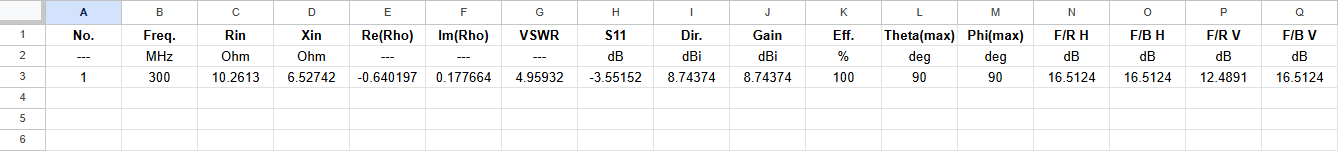
The primary output is a CSV (Comma-Separated Values) file named after your project with the suffix “_Results.csv” (e.g., Yagi-Uda3_Results.csv). This file contains comprehensive antenna metrics organized in columns, with each row representing data at a specific frequency.
For our Yagi-Uda example (set to 300 MHz), the file contains a single data row with the following parameters:
- No.: Row number
- Freq.: Frequency in MHz
- Rin: Feedpoint resistance (real part of input impedance) in Ohms
- Xin: Feedpoint reactance (imaginary part of input impedance) in Ohms
- Re(Rho) / Im(Rho): Real/imaginary parts of reflection coefficient (referred to 50 Ω)
- VSWR: Voltage Standing Wave Ratio (referred to 50 Ω)
- S11: Reflection coefficient in dB (referred to 50 Ω)
- Dir.: Peak directivity in dBi
- Gain: Peak gain in dBi
- Eff.: Radiation efficiency (%)
- Theta(max) / Phi(max): Zenith/azimuth angles of peak radiation (degrees)
- F/R H, F/B H: Front-to-Rear and Front-to-Back ratios (horizontal plane, Theta = Theta(max)) in dB
- F/R V, F/B V: Front-to-Rear and Front-to-Back ratios (vertical plane, Phi = Phi(max)) in dB
2. AN-SOF Project Files
The engine also generates a set of files compatible with the AN-SOF UI, following its distributed file system (detailed in File Formats). For our Yagi-Uda example:
- Yagi-Uda3.emm: Main project file (open via AN-SOF’s File > Open)
- Yagi-Uda3.wre: Wire geometry data
- Yagi-Uda3.cur: Current distribution
- Yagi-Uda3.phi/.the: Far-field components (azimuth/zenith)
- Yagi-Uda3.pwr: Radiation pattern metrics
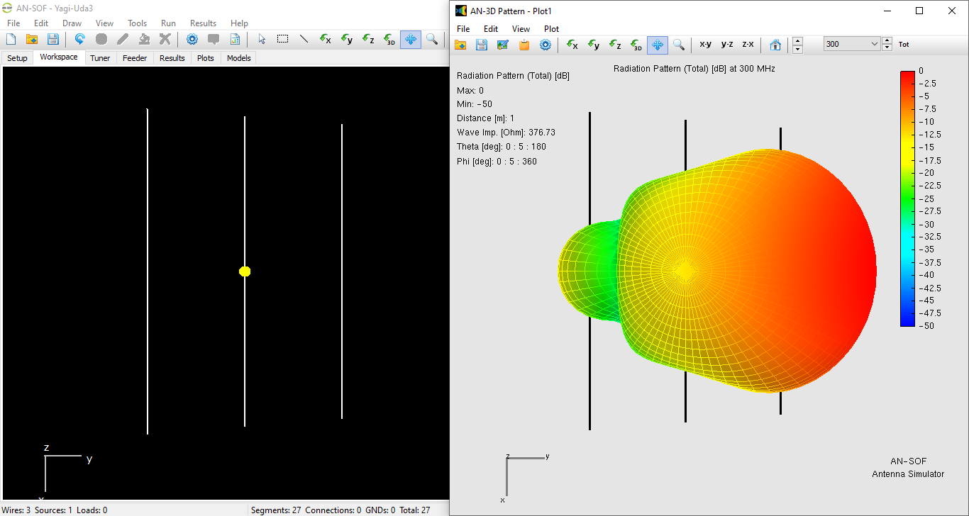
To visualize results:
- Open
Yagi-Uda3.emmin the AN-SOF UI to inspect the model and radiation patterns. - For recalculations, save modified designs as new
.necfiles and rerun them through the AN-SOF Engine.
Note: The standard AN-SOF UI may not support all Engine-compatible calculations—edits require Engine reprocessing to avoid errors.
Scope and Troubleshooting
Current Capabilities
The AN-SOF Engine in its current release supports the following wire geometries:
- Linear wires (
GWcommand) - Helices (
GHcommand) - Circular arcs (
GAandGBcommands)
Note that while the AN-SOF UI (with standard engine) supports additional wire types like quadratics and spirals, these are not yet available in the Engine. The Engine currently only supports discrete source excitations—incident wave excitation is not implemented.
For output data, the Engine calculates:
- Input impedance metrics: Resistance (Rin), reactance (Xin), reflection coefficient (Rho), VSWR, and S11.
- Far-field metrics: Directivity, gain, radiation efficiency, and front-to-rear/back ratios (F/R, F/B).
Near-field calculations are not supported in this release.
Troubleshooting Guide
Issue 1: No Output Files Generated
If the console closes without errors but output files are missing:
- Open the AN-SOF UI and navigate to Main Menu > Import Wires > NEC Format.
- Select your
.necfile. Any command errors will be displayed in the Setup tab’s error panel.
Issue 2: Far-Field Metric Discrepancies
Minor differences in far-field values (e.g., directivity, gain) between the Engine and standard UI are expected. The Engine’s results are more precise, though deviations are typically insignificant for practical applications.
Issue 3: “No Wires Could Be Imported” Error
This indicates invalid geometry commands (GW, GH, etc.). To debug:
- Import the
.necfile into the AN-SOF UI (File > Import Wires > NEC Format). - Correct any modeling errors flagged in the interface.
This concludes the AN-SOF Engine User Guide. For further assistance, contact technical support at info@antennasimulator.com.