Search for answers or browse our Knowledge Base.
Guides | Models | Validation | Book
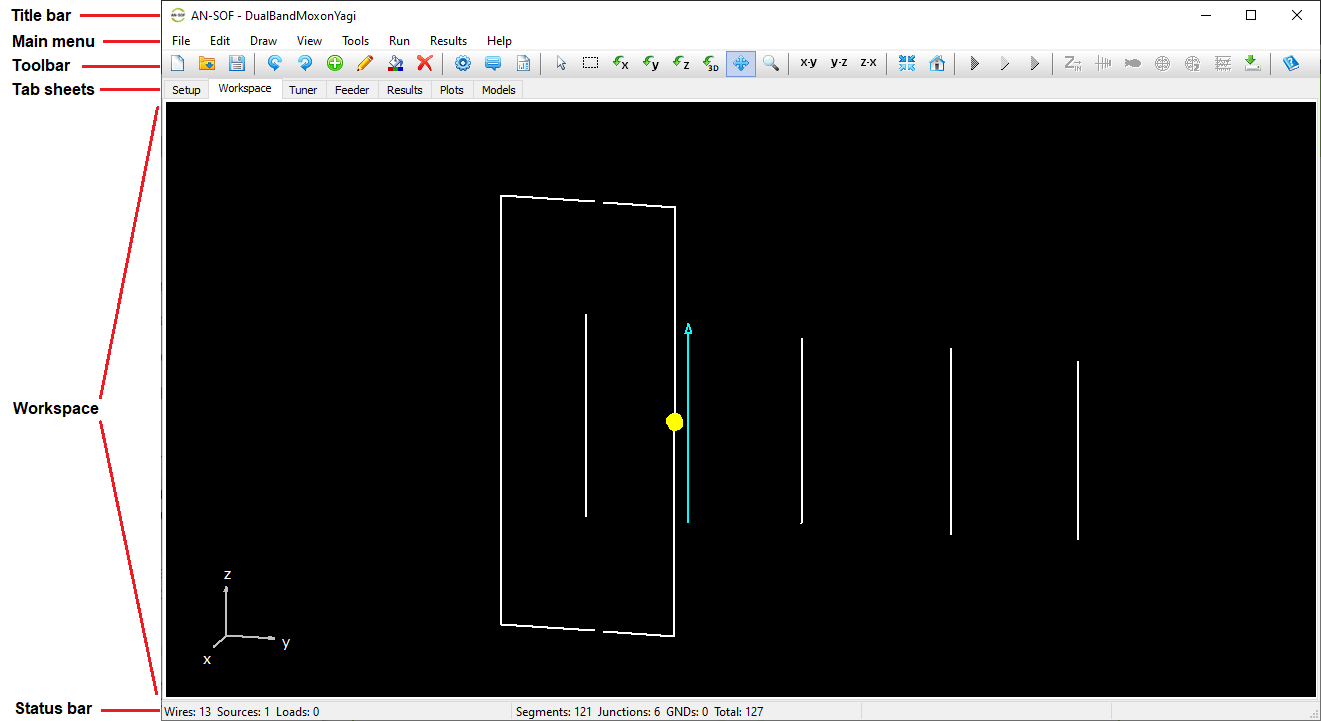
The AN-SOF Interface
Main Window and Menu
When AN-SOF starts, the main window displays several key components that form the core of the user interface (Fig. 1):
- Title Bar – Displays the name of the currently active project file (
.emmformat). - Main Menu Bar – Provides access to the primary menus: File, Edit, Draw, View, Tools, Run, Results, and Help.
- Toolbar – Contains icons for quick access to commonly used commands and tools.
- Tab Sheets – Allow users to switch between different stages of the workflow, from Setup to Plots, with a single click.
- Workspace – The central 3D canvas where wire structures are drawn and visualized.
- Status Bar – Displays real-time information, such as the number of segments, wire-to-wire junctions, and wire-to-ground connections (GNDs).
File Menu
The File menu provides commands for managing AN-SOF projects, including creating, opening, saving, importing, and exporting files. The available commands are:
- New… (Ctrl + N)
Creates a new project from scratch. - Open… (Ctrl + O)
Opens an existing project file (.emm) using the standard Open dialog. - Save (Ctrl + S)
Saves the current project under its existing name. - Save As…
Saves the current project with a new name. If the project is new, this command prompts the user to assign a name and location. - Import Wires
Opens a dialog to import wire data from various formats, including AN-SOF (.wre), NEC (.nec), and MM format (.txt). - Export Wires
Allows exporting the wire geometry to several formats:- NEC (
*.nec) - DXF (
*.dxf) - Scilab script (
*.sce) - MATLAB/Octave script (
*.m)
- NEC (
- Copy Workspace
Copies the current workspace view to the clipboard as a bitmap image. - Recent Files List
Displays up to ten recently opened project files for quick access. Use “Empty Recent Files List” to clear the history. - Exit (Ctrl + Q)
Closes the current project and exits AN-SOF.
Edit Menu
The Edit menu provides tools for modifying, organizing, and managing wires in your project. The available commands include:
- Undo (Ctrl + Z)
Reverts the project to the previous state before the last command was executed. - Redo (Ctrl + Y)
Reapplies the last undone action, restoring the project to the state before Undo was used. - Source / Load / TL (Ctrl + Ins)
Opens the Source/Load/TL toolbar, allowing you to add sources, loads, or connect transmission line (TL) ports to a selected wire segment. This command is enabled when a single wire is selected. - Modify (Ctrl + M)
Opens the Modify dialog box for editing properties of the selected wire(s). Available when one or more wires are selected. - Wire Color
Opens a standard color selection dialog to change the color of the selected wire(s). Enabled when one or more wires are selected. - Delete (Ctrl + Del)
Deletes the selected wire(s), including any attached sources or loads. Enabled when one or more wires are selected. - Copy Start Point
Copies the start point coordinates of the selected wire. This point can be used as the start of a new wire, enabling direct connection. Enabled when a wire is selected. - Copy End Point
Copies the end point coordinates of the selected wire for use as the starting point of a new, connected wire. Enabled when a wire is selected. - Start Point to GND
Draws a vertical wire from the start point of the selected wire down to the ground plane. This command is available only when a ground plane is defined in the model and a wire is selected. - End Point to GND
Draws a vertical wire from the end point of the selected wire down to the ground plane. Like the previous command, it is available when a ground plane exists and a wire is selected. - Move Wires… (Ctrl + Alt + M)
Opens the Move Wires dialog to reposition the selected wires. Enabled when at least one wire is selected. - Rotate Wires… (Ctrl + Alt + R)
Opens the Rotate Wires dialog to rotate selected wires around a specified axis. Enabled when at least one wire is selected. - Scale Wires… (Ctrl + Alt + S)
Opens the Scale Wires dialog to apply a scaling factor to the selected wires. Enabled when at least one wire is selected. - Copy Wires…
Opens the Copy Wires dialog to duplicate the selected wires, with options to apply translation or rotation to the copies. Enabled when at least one wire is selected. - Stack Wires…
Opens the Stack Wires dialog to generate multiple copies of the selected wires arranged along a specified direction. Enabled when at least one wire is selected.
Draw Menu
The Draw menu provides tools for creating a wide variety of wire geometries and wire grids. These commands allow users to model antenna elements with precision and flexibility. The available options include:
- Line
Opens the Line dialog box to draw a straight wire between two defined endpoints. - Arc
Opens the Arc dialog to draw a circular arc segment. - Circle
Opens the Circle dialog to draw a complete circular loop. - Helix
Opens the Helix dialog to create a helical wire, often used in axial-mode antennas. - Quadratic
Opens the Quadratic dialog to draw a curved wire defined by a quadratic function. - Archimedean Spiral
Opens the Archimedean Spiral dialog to draw a spiral with uniform spacing between turns. - Logarithmic Spiral
Opens the Logarithmic Spiral dialog to create a spiral with exponentially increasing spacing—ideal for frequency-independent antenna designs.
Wire Grid / Solid Surface
This option creates a wire grid or a discretized surface geometry. It includes the following sub-commands:
- Patch – Draws a rectangular mesh on the xy-plane.
- Plate – Creates a bilinear surface or flat panel.
- Disc – Draws a flat circular disc.
- Flat Ring – Draws a ring-shaped disc with a central hole.
- Cone – Creates a conical surface structure.
- Truncated Cone – Draws a cone with a flat top (cut-off cone).
- Cylinder – Draws a cylindrical surface.
- Sphere – Creates a spherical grid or surface.
- Paraboloid – Draws a parabolic reflector surface.
Tapered Wire
This option allows drawing wires with stepped-radius profiles, useful for simulating tapered elements such as monopoles or matching sections. Each command mirrors the standard wire options above (e.g., Line, Arc, Helix), but with the ability to assign different radii along the length.
- Tabular Input (Ctrl + T)
Opens a spreadsheet-style table for entering linear wires, sources, loads, and transmission lines numerically—ideal for precise control and batch input. - Transmission Lines (Ctrl + L)
Opens a dedicated table to define transmission lines by specifying their characteristic impedance, velocity factor, length, and loss parameters.
View Menu
The View menu provides options to control the display of interface elements, adjust zoom levels, and access additional project and wire information. Use these commands to customize your workspace and enhance your modeling experience:
- Wire Properties… (Ctrl + W)
Opens the Wire Properties dialog, showing detailed information about the selected wire. This command is available when a wire is selected. - Project Details…
Opens the Project Details dialog, displaying a summary of the current project, including the number of segments, wires, sources, and loads. - Zoom In (Ctrl + I)
Magnifies the view within the workspace. You can also zoom in by scrolling the mouse wheel backward. - Zoom Out (Ctrl + K)
Reduces the view scale in the workspace. You can also zoom out by scrolling the mouse wheel forward. - Reset Zoom Scale
Resets the zoom level and resizes the workspace to fit the entire structure. - Axes… (Ctrl + A)
Opens the Axes dialog to adjust the appearance of the coordinate axes. Press F7 to toggle between the small axes (shown in the lower-left corner) and the main axes (centered in the workspace). - X-Y Plane / Y-Z Plane / Z-X Plane
Switches the view to align the selected plane (XY, YZ, or ZX) parallel to the screen, offering easier modeling and inspection from different perspectives. - Center
Centers the view on the structure in the workspace without altering the zoom level. - Initial View (Home)
Resets the workspace to the default orientation and zoom level. - Drawing Panel
Displays a panel on the left side of the workspace with quick-access buttons for drawing wires, wire grids/solid surfaces, and tapered wires.
Tools Menu
The Tools menu provides access to plotting tools, wire checking utilities, and other helpful features for project analysis and customization. The commands available in this menu include:
- 3D Chart
Launches the AN-3D Pattern application to open and view 3D radiation pattern files (.p3d). - Polar Chart
Launches the AN-Polar application for displaying polar radiation patterns from.plrfiles. - Rectangular Chart
Launches the AN-XY Chart application to view rectangular (Cartesian) plots from.pltfiles. - Smith Chart
Launches the AN-Smith application to display impedance or reflection coefficient data from.sthfiles using a Smith chart. - Check Individual Wires
Verifies the segment length, cross-sectional size, and thin-wire ratio for each wire. Wires that fall outside acceptable ranges are highlighted in yellow (warning) or red (error). - Check Wire Spacing
Analyzes the spacing between adjacent wires to ensure they are sufficiently separated. Wires with spacing issues are also highlighted in yellow or red. - Delete Duplicate Wires
Automatically detects and removes duplicate or overlapping wires from the project. - RF Calculators
Opens a webpage with a collection of online tools for calculating antenna parameters, propagation metrics, component values, and unit conversions. - Calculator
Launches the built-in Microsoft Windows® Calculator for quick arithmetic operations. - Preferences…
Opens the Preferences dialog box, where users can configure unit systems, workspace appearance, pen width, confirmation prompts, and other interface settings.
Run Menu
The Run menu provides commands to execute the simulation of currents and electromagnetic fields. These options allow users to selectively perform calculations depending on their analysis needs:
- Run Currents and Far-Field (F10)
Calculates the current distribution on the wire structure, from which input impedance and VSWR are derived, along with the far-field radiation pattern, used to compute radiation efficiency, gain, and front-to-back ratio. - Run Currents and Near-Field (F11)
Calculates the current distribution and the near electric and magnetic fields around the antenna structure. - Run ALL (F12)
Executes a complete simulation including currents, far-field, and near-field calculations in a single step. - Run Currents (Ctrl + R)
Calculates only the current distribution on the wire structure.
This is useful when interested solely in input parameters (impedance, reflection coefficient, VSWR), avoiding the time cost of field computations.
Note: This command is disabled when the currents have already been computed. - Run Far-Field
Calculates the far-field radiation pattern based on previously computed currents.
Enabled only after the current distribution has been calculated. - Run Near E-Field
Computes the near electric field generated by the current distribution.
Requires prior current calculation. - Run Near H-Field
Computes the near magnetic field generated by the current distribution.
Requires prior current calculation. - Run Bulk Simulation
Opens a dialog to select multiple input files in NEC format (.nec). AN-SOF will import each file, run the simulation, and export the results as CSV files to the same directory. This is ideal for batch processing multiple designs.
Results Menu
The Results menu provides a set of commands for visualizing and exporting simulation results. These include current distributions, field patterns, power metrics, and spectral data. The available commands are as follows:
Plot Current Distribution
Launches the AN-3D Pattern application to visualize the current distribution as a color pattern mapped onto the wire structure.
Plot Currents
Opens the AN-XY Chart to plot the magnitude and phase of currents versus position along a selected wire. This command is enabled only when a wire is selected.
List Currents…
Displays the List Currents toolbar to show current values versus frequency at a specific segment on a selected wire. If the segment includes a source, additional data such as input impedance, voltage, and power versus frequency will also be available. This command is enabled only when a wire is selected.
Export Currents
Exports the current distribution along a wire to a CSV file, including position and frequency-dependent data. Enabled only when a wire is selected.
List Input Impedances…
Shows a table of input impedances versus frequency, including associated parameters such as reflection coefficient, VSWR, return loss, and transmission loss at the antenna terminals.
Plot Far-Field Pattern
Opens a sub-menu with commands for plotting the radiation pattern in various formats:
- 3D Plot: Launches AN-3D Pattern to visualize the full 3D far-field radiation pattern.
- Polar Plot 1 Slice: Opens a dialog to select a single 2D slice of the far-field pattern, displayed in polar coordinates using AN-Polar.
- Polar Plot 2 Slices: Allows selection of two 2D slices of the far-field pattern, displayed in polar coordinates using AN-Polar.
- 2D Rectangular Plot: Allows selection of a 2D slice of the far-field pattern, displayed in rectangular (Cartesian) coordinates using AN-XY Chart.
Plot Far-Field Spectrum
Opens a dialog to select a point in space where far-field components will be analyzed across frequency. The spectrum is displayed using AN-XY Chart.
List Far-Field Pattern
Displays a table of the total electric field and its components (E-theta, E-phi, right-hand and left-hand circular polarization) at the theta–phi angular grid defined in the Far-Field panel. The data can be exported as a CSV file.
List Far-Field Spectrum
Opens a dialog to select a spatial point where the far-field components will be listed versus frequency. The table includes the total E-field and its components: E-theta, E-phi, right-hand and left-hand polarized components. The data can be exported as a CSV file.
Power Budget / RCS
Displays the Power Budget dialog showing total input power, radiated and consumed power, power density, efficiency, directivity, and gain as functions of frequency. For simulations with plane wave excitation, the Radar Cross Section (RCS) versus frequency is shown.
Plot Near E-Field Pattern
Opens a sub-menu for near-field electric field visualization:
- 3D Plot: Launches AN-3D Pattern to show a 3D visualization of near E-field components.
- 2D Plot: Opens the Near-Field Cut dialog for selecting and plotting a 2D cut using AN-XY Chart.
Plot Near E-Field Spectrum
Opens a dialog to select a spatial point and plots the frequency response of the near E-field components using AN-XY Chart.
List Near E-Field Pattern
Displays a table of the total near electric field and its components at the grid defined in the Near-Field panel. The data can be exported as a CSV file.
List Near E-Field Spectrum
Opens a dialog to select a point in space and displays the near E-field spectrum in table format, including the individual field components versus frequency. The data can be exported as a CSV file.
Following these commands, similar options are available for Near H-Field and Power Density data. To compute power density, both the near E-field and H-field must have been previously calculated, as power density is obtained from the vector (cross) product of these fields at each spatial point.
Help Menu
Use the Help menu to access the user guide, technical support, license activation, and version information. This menu includes:
- User Guide
Opens the AN-SOF User Guide in PDF format. - AN-SOF Home Page
Opens the official website at www.antennasimulator.com in your default browser. - Knowledge Base
Opens the Knowledge Base where you can search categorized help articles and how-to guides. - Email to Tech Support
Launches your default email client to send a support request to info@antennasimulator.com. - Chat to Tech Support
Opens the live chat support page in your default browser. - Activate AN-SOF
Runs the AN-Key application, which shows your PC’s serial number and allows you to enter an activation key to license the software. - Check for Updates
Opens the webpage with the latest AN-SOF software releases. - About AN-SOF…
Displays version number, license, and copyright.
Main Toolbar
The main toolbar provides quick access to essential commands, many of which are also found in the main menu. In addition, it includes extra tools not available in the menu.
One such group consists of 3D View Controls, which help users interact with the 3D workspace (see Fig. 2):

3D View Controls
- Select Wire (arrow icon)
Activates selection mode. Click a wire to select it. To select multiple wires, hold Ctrl and click each one. Selected wires are highlighted in light blue. To deselect, Ctrl + click again, or double-click in the workspace or press ESC to clear all selections. - Selection Box
Allows selecting multiple wires by dragging a box with the left mouse button:- Drag from top to bottom to select only wires fully enclosed.
- Drag from bottom to top to select any wires that intersect the box.
- Previously selected wires will be deselected if included again.
- Double-click the workspace or press ESC to deselect all.
- Rotate around X/Y/Z
Rotates the view around the selected axis (X, Y, or Z) by moving the mouse in the workspace. - 3D Rotation
Enables free rotation around all axes by moving the mouse in the workspace. - Move (cross icon)
Pans the view by dragging the mouse with the left button held down. - Zoom (magnifying glass icon)
Lets you zoom into a selected area by dragging a rectangle. After zooming, use the mouse wheel to adjust the zoom level.
Other Toolbar Commands
- Export Results
Located next to the results-related buttons, this command exports the data in the Results tab to a CSV file.