Search for answers or browse our Knowledge Base.
Guides | Models | Validation | Book
Automotive Antenna Placement: How Vehicle Geometry Reshapes FM Reception
Is your car antenna truly omnidirectional? Discover how vehicle geometry reshapes FM signals in this AN-SOF study of a 100 MHz monopole. We compare roof-mount and trunk-mount placements, revealing how induced surface currents and body diffraction create unexpected directional gain and reception bias.
Introduction: The Vehicle as a Radiator
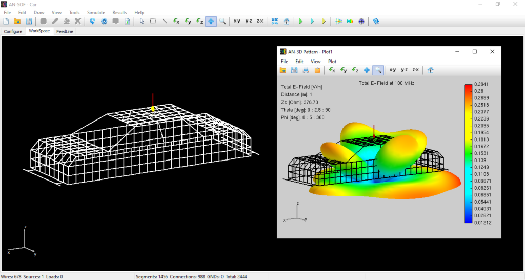
In automotive engineering, the location of an antenna is often a compromise between aesthetics, aerodynamics, and RF performance. However, at FM frequencies (88–108 MHz), a vehicle is not just a mounting bracket; it is a complex electromagnetic scatterer. When a vertical monopole is mounted on a car, the metallic body supports induced surface currents that contribute significantly to the total far-field radiation pattern.
This article analyzes a 19.6-inch vertical monopole integrated into an average sedan (184″ x 64″ x 40″) modeled at 100 MHz. Using AN-SOF’s wire-grid modeling, we demonstrate how the physical “ground plane” of the car body tilts, focuses, and diffracts the signal, leading to surprisingly directional results.
Simulation Methodology & Setup
To isolate the interaction between the antenna and the vehicle body, the following parameters were used:
- Platform: A wire-grid representation of a sedan’s external metallic surface.
- Ground Environment: A Perfect Electrical Conductor (PEC) ground plane situated 16 inches below the vehicle.
- The “Near-Far” Perspective: By using a PEC ground, we eliminate ground-wave attenuation variables, allowing the far-field pattern to represent the Transverse Electromagnetic (TEM) field distribution in the intermediate zone, far enough to be beyond reactive near-fields, but close enough to visualize how the car’s shape “sculpts” the signal.
- Excitation: A 1-volt source at the base of the monopole.
Case 1: The Roof-Mounted Monopole
The center of the roof is often considered the “ideal” location due to its height and relative symmetry. However, our AN-SOF simulation reveals a more complex reality.
Observations:
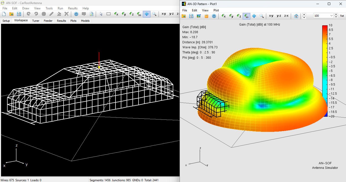
- Peak Gain: 8.2 dBi.
- Directivity: The pattern is predominantly rearward-facing (Fig. 1).
- Physics of the Pattern: At 100 MHz, the roof acts as a finite ground plane. The currents induced on the roof and the sloping rear window (C-pillar area) create a directive effect. The “tilt” of the car’s profile from the roof down to the trunk acts as a quasi-tapered transition, reinforcing the radiation toward the back of the vehicle.
By the Principle of Reciprocity, this means a car with a center-roof antenna will inherently exhibit better reception sensitivity to FM stations located behind the vehicle.
Figure 1 shows the car model with the roof monopole antenna in the AN-SOF workspace, along with the 3D gain pattern. The model can be downloaded via the button below the figure.
Case 2: The Trunk-Mounted Monopole
Moving the antenna to the center of the trunk yields a surprising reversal of the radiation characteristics.
Observations:
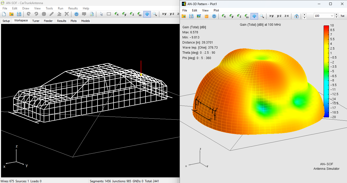
- Peak Gain: 6.6 dBi.
- Directivity: The pattern points preferentially toward the front of the vehicle (Fig. 2).
- Physics of the Pattern: When placed on the trunk, the most significant “obstacle” is the rest of the car’s body (the cabin and engine block). The vertical bulk of the cabin acts similarly to a parasitic ‘director’ element in a Yagi-Uda array, diffracting energy over the roof and toward the front. The lower gain (6.6 dBi vs 8.2 dBi) is due to the increased shadowing and multi-path interaction with the car’s pillars.
The car model, featuring the trunk-mounted monopole antenna, is displayed in the AN-SOF workspace in Figure 2, which also includes the 3D gain pattern. A download button for the model is located below the figure.
Comparative Analysis: The Shadowing Effect
Both simulations showed significant lateral lobes. These are caused by the width of the vehicle (64 inches $\approx 0.54\lambda$). At this width, the car body supports transverse resonances that “leak” energy to the sides.
The contrast between the two placements highlights a critical rule in automotive CEM: The bulk of the vehicle mass opposite the antenna often acts as the primary “director” or “reflector” for the signal.
- Roof Mount: Higher gain, better rearward coverage.
- Trunk Mount: Lower gain, better forward coverage.
Conclusions
This study proves that “omnidirectional” monopoles become directional the moment they are integrated into a vehicle platform. At FM frequencies, the car body behaves as a resonant cavity and a parasitic radiator.
For the RF designer, these results suggest that:
- Diversity is Key: To achieve true 360-degree FM coverage, modern vehicles often require diversity systems (multiple antennas) to fill the “nulls” created by the vehicle’s body.
- Platform Awareness: Simulation in AN-SOF is essential before final hardware placement, as the “geometric center” of a surface rarely correlates to the “electromagnetic center” of the radiation pattern.
See Also:
Technical Keywords: Automotive CEM, Monopole Antenna, Platform Integration, Wire-Grid Modeling, 100 MHz FM, Far-Field Pattern, Reciprocity.
