Search for answers or browse our Knowledge Base.
Guides | Models | Validation | Book
Boosting Performance with Dual V Antennas: A Practical Design and Simulation
Learn how stacking two V antennas can boost directivity. This article presents a practical Dual V Antenna design and explains how to scale it for any frequency. Includes simulation insights and a link to an online calculator.

The V antenna is a well-known long-wire traveling wave antenna prized for its simplicity and high directivity. By angling two long wires symmetrically in a V-shape, this antenna creates a highly directional beam, making it a favorite in both amateur and professional applications.
For those seeking a deeper understanding of how to optimize V antennas—including how to calculate directivity and the ideal angle between legs—a detailed explanation is available in the article Validating V Antennas: Directivity Analysis with AN-SOF. That article also includes an interactive calculator to assist with design decisions.
In this article, we go a step further by examining a more advanced configuration: the Dual V Antenna. This design involves two identical V antennas arranged vertically, one placed directly above the other. When properly spaced and phased, this array further increases the overall directivity beyond what a single V antenna can achieve.
The Dual V Antenna Model
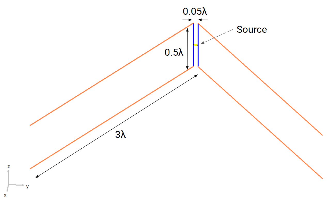
The model is simulated at 300 MHz, a convenient frequency where the wavelength is approximately 1 meter, which simplifies dimensional scaling. The two V antennas are separated vertically by half a wavelength (0.5λ), forming a two-element array. To adapt the model for a different frequency, simply scale all dimensions by the new wavelength.
Each V antenna consists of two horizontal legs, each 3λ in length, angled outward from a central vertex. The legs are inclined at 60°, which is slightly wider than the 55.5° angle that yields optimal directivity for a single V antenna of the same length, according to the V antenna online calculator. This small adjustment accounts for the influence of the second V antenna in the array.
The vertices of the two V antennas are connected by vertical wires, forming a twin-lead structure resembling a two-wire transmission line. The feedpoint is located at the midpoint of this vertical line, where a voltage source is applied in the AN-SOF model.
Fig. 1 shows the antenna dimensions in wavelengths. The vertical wires forming the transmission line are spaced 0.05λ apart, as a small spacing is required for this section to function effectively as a transmission line. A wire radius of 1 mm is used for all elements. Both the spacing between the transmission line wires and the wire radius influence the input impedance, so it’s important to experiment with different wire thicknesses and spacings to achieve the desired match.
Simulation Results
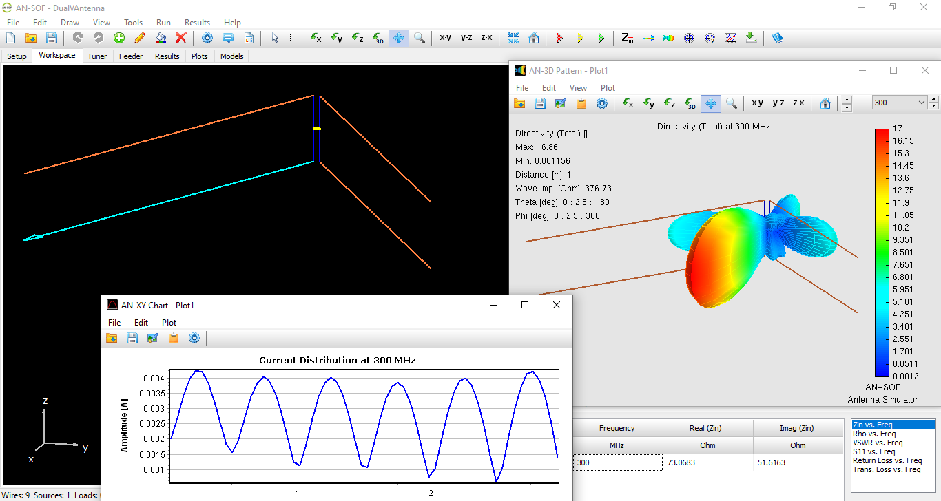
The simulation shows a maximum directivity of 12.3 dBi—an improvement over the 10 dBi predicted by the online calculator for a single V antenna with 3λ legs. This increase in gain is attributed to the constructive interference between the radiation fields of the two vertically stacked antennas.
The radiation resistance of the structure is 73 + j52 Ohms, making it reasonably straightforward to match to standard 75-ohm coaxial lines with minimal impedance transformation.
The simulation results are summarized in Fig. 2. The dual V antenna model is displayed in AN-SOF’s workspace on the left, the radiation pattern is shown on the right, and the input impedance is presented at the bottom right. An inset in Fig. 2 illustrates the current distribution along a leg, showing six sine-like semicycles. This matches the expected behavior for a wire 3 wavelengths long, as two semicycles occur per wavelength.
Final Thoughts
The Dual V Antenna provides an elegant way to achieve higher directivity using a relatively simple structure. By stacking two V antennas and carefully controlling spacing and feeding, designers can extract more performance without resorting to more complex array geometries.
Whether you’re an antenna experimenter, a ham radio operator, or an RF design engineer, this configuration offers a compelling blend of performance, simplicity, and scalability.
To dive deeper into the theory and start experimenting with your own V antenna designs, visit the full article here:
