Search for answers or browse our Knowledge Base.
Guides | Models | Validation | Book
Simulating Helical Antennas over Finite Wire-Grid Ground Planes
Learn how to simulate axial-mode helical antennas using AN-SOF. This study analyzes LHCP gain, impedance, and axial ratio over a finite wire-grid ground plane from 75 to 95 MHz.
Introduction
The axial-mode helical antenna is a premier choice for applications requiring circular polarization and high directivity, such as satellite tracking and long-range VHF/UHF communications. Unlike the normal-mode helix, which radiates omnidirectionally, the axial-mode helix acts as a high-gain end-fire radiator. In this article, we analyze a Left-Handed (LH) helix design simulated in AN-SOF, focusing on the broadband stability of gain and the impact of a finite wire-grid ground plane.
Design Parameters & Geometry
The antenna was modeled to operate across the 75–95 MHz band. A critical aspect of helical simulation is the discretization of the curved conductor. By using AN-SOF’s Conformal Method of Moments (CMoM), we achieve superior numerical convergence compared to standard piecewise-linear approximations.
Helix Specifications:
- Handedness: Left-Handed (LH)
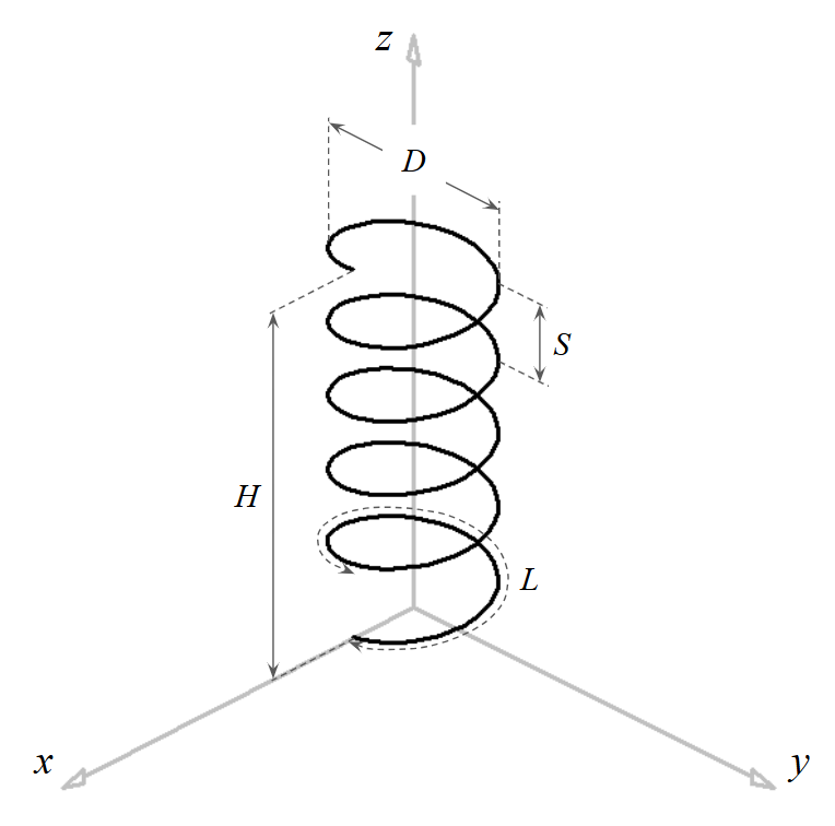
- Radius: $0.477\text{ m}$ (Diameter: $D = 0.954\text{ m}$)
- Pitch: $S = 0.692\text{ m}$
- Number of Turns: $N = 10$
- Pitch Angle: $\alpha = \tan^{-1}(S/(\pi D)) \approx 13^\circ$
- Total Height: $H = N \cdot S = 6.92\text{ m}$ (Fig. 1)
The helix is discretized into 120 segments (12 per turn), ensuring that segment length is significantly smaller than $\lambda/10$ even at the highest frequency (95 MHz), satisfying the CMoM requirements.
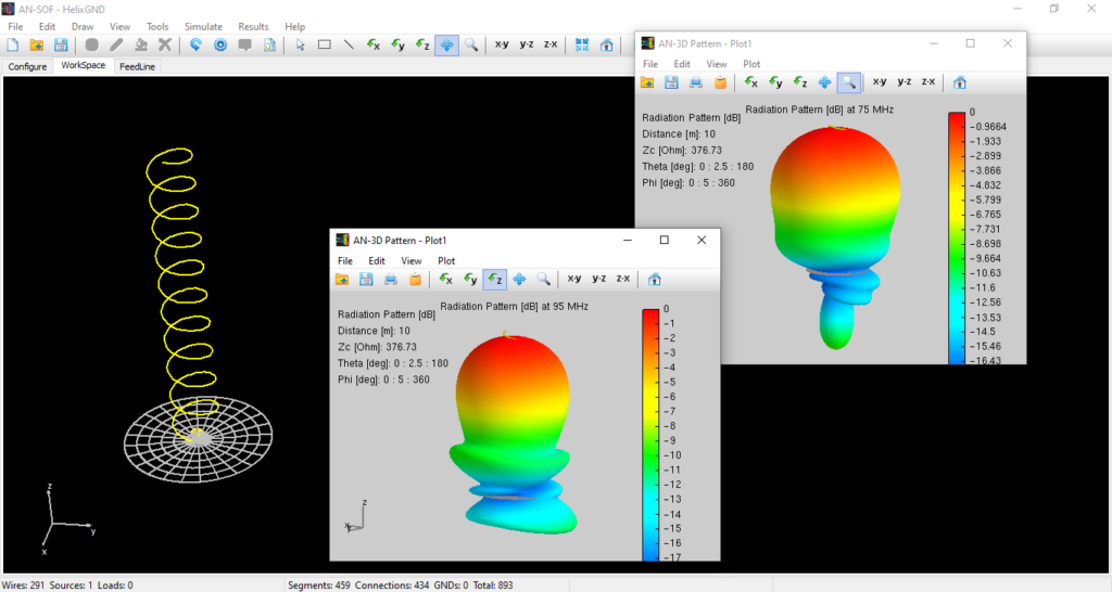
Ground Plane Modeling: The Wire Grid Approach
To simulate a realistic finite environment, a circular ground plane with a radius of $1.5\text{ m}$ was implemented (Fig. 2). In Method of Moments (MoM) solvers, solid surfaces are effectively modeled as a mesh of wires. We utilized a circular grid divided into:
- Radial Divisions: 6
- Circumferential Divisions: 24
This $6 \times 24$ facet configuration provides a robust reflective surface that correctly captures the edge diffraction effects that a simple infinite-plane mathematical model would ignore.
To download the complete helix model, click the button located beneath Fig. 2.

Simulation Results & Analysis
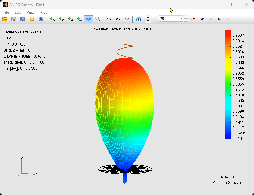
1. Radiation Pattern and Gain
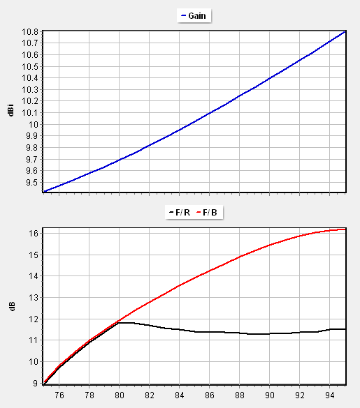
The simulation confirms a stable, directional main lobe pointing along the helix axis (opposite the ground plane, Fig. 3). The gain remains remarkably constant at approximately $10\text{ dBi}$ across the entire $20\text{ MHz}$ bandwidth.
The Front-to-Back (F/B) ratio varies between $10$ and $16\text{ dB}$ (Fig. 4). This variation is primarily due to the finite size of the ground plane; at $75\text{ MHz}$, the $1.5\text{ m}$ radius ground plane is roughly $0.37\lambda$, meaning surface currents reaching the edges contribute to back-lobe radiation.
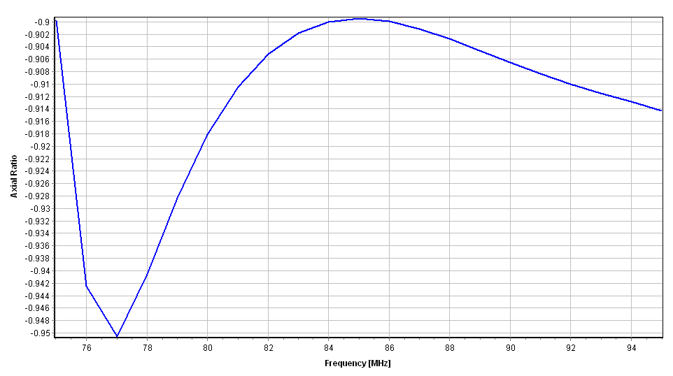
2. Polarization Purity
As a left-handed helix, the antenna produces Left-Hand Circular Polarization (LHCP). The Axial Ratio ($|AR|$) is a critical metric for polarization purity, where $1.0$ represents a perfect circle.
- Observed $|AR|$: $0.9$ to $0.95$ (Fig. 5)
This high purity indicates that the phase quadrature between the horizontal and vertical components of the radiated field is well-maintained, a direct result of the optimized $13^\circ$ pitch angle.
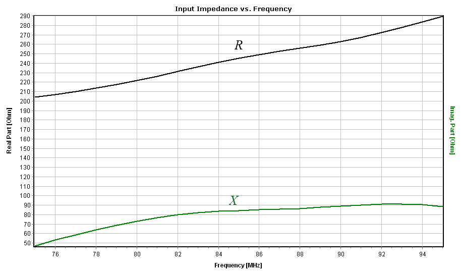
3. Input Impedance
The input impedance of an axial-mode helix is typically high and primarily resistive. For this model, AN-SOF calculated:
$Z_{in} \,=\, (200 \text{ to } 280) \,+\, j(50 \text{ to } 80) \, \Omega$
The significant real part ($>200\,\Omega$) is characteristic of the axial mode (Fig. 6). To interface this with standard $50\,\Omega$ coaxial systems, a matching network is required, such as a $\lambda/4$ transformer or a tapered microstrip transition at the feed point.
Conclusion
This AN-SOF model demonstrates the classic broadband characteristics of the axial-mode helical antenna. The stability of the gain and the axial ratio across the 75–95 MHz range highlights the antenna’s relative immunity to minor frequency shifts. For engineers, the high input impedance remains the primary design challenge, requiring careful attention to the feedpoint geometry to ensure maximum power transfer.
See Also:
Technical Keywords: LHCP (Left-Hand Circular Polarization), Axial Ratio (AR), Finite Ground Plane Modeling, Method of Moments (MoM), 85 MHz Helix Design.
