Search for answers or browse our Knowledge Base.
Guides | Models | Validation | Book
Design and Simulation of a Compact Self-Resonant Pyramidal Horn Antenna for 2.4 GHz WiFi
Explore a compact, self-resonant pyramidal horn antenna designed for the 2.4 GHz WiFi band. This study challenges traditional aperture theory by demonstrating how an electrically small horn, with an axial length of just half a wavelength, can achieve a high gain of 13 dBi. Through AN-SOF wire-grid simulation, we detail the waveguide feed optimization and flare-angle geometry required to bridge the gap between idealized textbook formulas and practical, high-performance DIY antenna construction.

Introduction to the Pyramidal Horn
The horn antenna is one of the most recognizable and widely used radiators in microwave engineering. Conceptually, it acts as a “transformer” or a tapered transition between the constrained environment of a rectangular waveguide and the unconstrained environment of free space. By gradually flaring the waveguide dimensions, the antenna matches the low characteristic impedance of the waveguide to the higher impedance of free space ($377\ \Omega$), thereby minimizing reflections and forming a highly directional beam.
While pyramidal horns (Fig. 1) are typically associated with large-scale satellite communications where they reach lengths of 10 wavelengths ($\lambda$) or more, such dimensions are often impractical for DIY enthusiasts or compact wireless integration. At the standard 2.4 GHz WiFi band ($\lambda \approx 123 \text{ mm}$), a 10$\lambda$ horn would exceed one meter in length. This article examines a “compact” or “electrically small” horn design with an axial length of approximately $0.5\lambda$, optimized for self-resonance and 14 dBi gain using AN-SOF wire-grid simulation.
The Limitation of Aperture Theory in Small Horns
In classical antenna theory, the gain ($G$) of a horn is often estimated based on its physical aperture area ($A$) using the formula:
$\displaystyle G \,=\, \frac{4\pi A}{\lambda^2} \cdot \eta_{ap}$
Where $\eta_{ap}$ is the aperture efficiency. For an ideal, 100% efficient aperture with the dimensions adopted in this study, $a_e = 1.1\lambda$ and $a_h = 1.7\lambda$, the calculation yields:
$\displaystyle G \,=\, 4\pi \, (1.1 \times 1.7) \,=\, 23.5 \implies 13.7 \text{ dBi}$
However, this theoretical formula assumes that the phase of the electromagnetic field is uniform across the aperture. In compact horns with wide flare angles and electrically short axial lengths, the phase center is located deep within the horn, causing a significant phase error at the edges of the aperture. This phase deviation reduces the effective gain and alters the radiation pattern. Consequently, for an electrically small horn where the axial length is only $\sim 0.5\lambda$, analytical formulas become inaccurate, necessitating the use of full-wave numerical simulation to characterize the true performance.
Geometric Configuration and Design Guidelines
The design follows specific ratios intended to balance impedance matching with directivity. The pyramidal flare is designed with an optimal aperture ratio of approximately 3:2 and a waveguide side ratio of 2:1.
Horn Dimensions at 2445 MHz:
- Aperture Height: $a_e = 1.1\lambda$ (E-plane flare).
- Aperture Width $a_h = 1.7\lambda$ (H-plane flare).
- Axial Length: $L = 0.52\lambda$.
- Flare Angles: $\theta_e = 73^\circ$ and $\theta_h = 78^\circ$.
Waveguide and Excitation:
The horn is fed by a rectangular waveguide section with dimensions $a \times b \times c = 0.84\lambda \times 0.32\lambda \times 0.89\lambda$ (Fig. 2). Excitation is provided by a vertical monopole pin (feed probe) positioned inside the waveguide.
- Pin Height: $h = 0.22\lambda$.
- Pin-to-Back-Wall Distance: $d = 0.2\lambda$.
This “pin-feed” mechanism excites the fundamental $TE_{10}$ mode within the waveguide. The distance $d$ is critical; it is tuned so that the back-radiated wave reflects off the rear wall and arrives back at the pin in-phase with the forward wave, maximizing power transfer toward the horn’s mouth.
Numerical Results and Impedance Analysis
The model was simulated using a wire-grid discretization in AN-SOF across a frequency sweep from $2255$ to $2700 \text{ MHz}$. Despite the simplified grid density, the results provide a clear view of the antenna’s wideband nature and resonant characteristics (Fig. 3).
Input Impedance and VSWR:
At the center frequency of $2445 \text{ MHz}$, the antenna exhibits an input impedance of $55 \,-\, j15\ \Omega$. When referenced to a standard 50-Ohm system, the VSWR is $1.3$, indicating an excellent match without the need for external tuning components.
The bandwidth performance is notably robust. For a VSWR threshold of $\le 1.5$, the antenna maintains a 9% bandwidth. If evaluated using the $S_{11} < -10 \text{ dB}$ return loss criteria, the bandwidth extends across the entire simulated sweep (Fig. 4), confirming the horn antenna’s inherent advantage in stability over narrow-band resonators like patches.
Radiation Characteristics
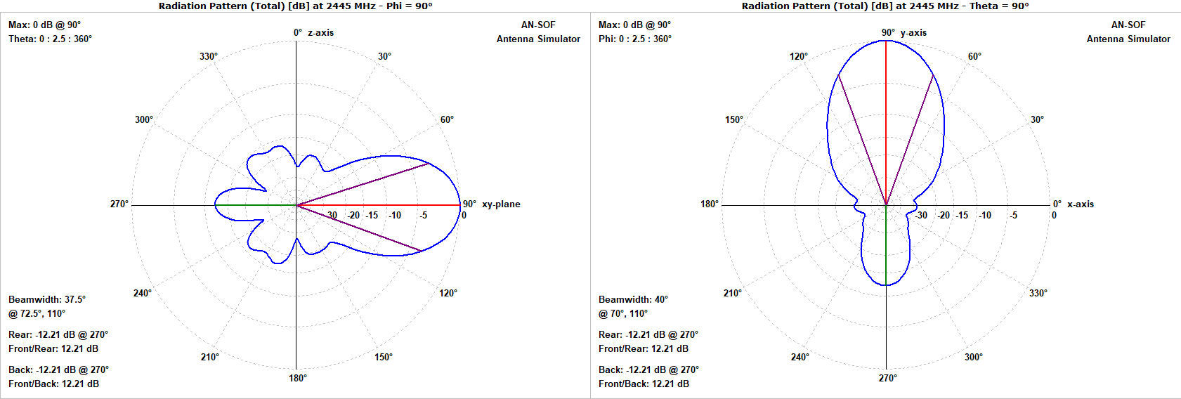
The far-field analysis reveals a well-behaved, directional beam optimized for point-to-point links (Fig. 5).
- Gain: The gain varies from $12.6$ to $13.5 \text{ dBi}$ across the band. This is remarkably close to the theoretical maximum of $13.7 \text{ dBi}$, suggesting that the wide flare angles and short length are highly efficient at this specific frequency.
- Beamwidth: The Half-Power Beamwidth (HPBW) is nearly symmetrical, with $38^\circ$ in the E-plane and $40^\circ$ in the H-plane. This “pencil beam” characteristic allows for precise targeting of WiFi signals.
- Front-to-Back (F/B) Ratio: The F/B ratio ranges from $13$ to $10 \text{ dB}$. While lower than a large horn, it is typical for an electrically small structure where diffraction around the edges of the aperture contributes to rearward radiation.
Practical Applications
The compact nature and 13 dBi gain of this design make it a versatile tool for various 2.4 GHz applications:
- DIY WiFi Range Extension: For hobbyists, this compact horn can be constructed from copper-clad PCB or sheet metal. It offers a significant upgrade over standard dipole or “cantenna” designs, providing high directivity for extending the range of a wireless network between buildings.
- RF Site Surveys: Due to its predictable beamwidth and wide bandwidth, the horn is an excellent tool for measuring signal strength and identifying sources of interference in complex RF environments.
- Feed Element for Parabolic Dishes: While high-gain on its own, this compact horn is perfectly sized to serve as a high-efficiency feed for a parabolic reflector. Placing this horn at the focal point of a dish could easily push the system gain above 24 dBi for long-range backbone links.
Conclusion
The simulation of this compact pyramidal horn demonstrates that even with an axial length of only $0.52\lambda$, high performance can be achieved through careful tuning of the waveguide feed and flare angles. By moving away from inaccurate aperture-area generalizations and utilizing numerical full-wave simulation, designers can confidently build “small-form-factor” horns that provide professional-grade gain and VSWR for WiFi and other 2.4 GHz ISM band applications.
See Also:
Technical Keywords: Pyramidal Horn Antenna, Waveguide Feed, Aperture Efficiency, Self-Resonance, 2.4 GHz WiFi, AN-SOF Simulation, VSWR, Flare Angle, E-plane and H-plane.
