Search for answers or browse our Knowledge Base.
Guides | Models | Validation | Book
Modeling an Inverted V Antenna for 40 Meters: Design Insights and Ground Effects
The Inverted V antenna is a cornerstone of HF communication, providing a space efficient and single mast supported alternative to the horizontal dipole. This guide examines the critical influence of the antenna height above ground on its radiation pattern. Furthermore, we demonstrate how to use AN-SOF to accurately model the feedpoint at the antenna apex, enabling precise VSWR and gain predictions, an advantage often absent in traditional simulation tools.

Introduction
The inverted V antenna is a popular configuration among amateur radio operators due to its simplicity, compact footprint, and effective performance on the lower HF bands. Often compared to the classic dipole, the inverted V achieves similar radiation characteristics with a reduced horizontal span, making it well suited for installations with limited space. However, despite its popularity, many overlook how critical parameters such as wire angle, height above ground, and ground conductivity affect its performance. In this article, we take a closer look at a 40 meter inverted V antenna model, highlight key considerations when simulating such a structure, and clarify a common confusion: the inverted V is not a V beam.
Understanding the Inverted V Antenna
The inverted V is essentially a dipole with its legs sloped downward from a central, elevated feedpoint. This geometry introduces subtle but important differences in impedance, radiation pattern, and ground interaction compared to a flat-top dipole.
A typical design for the 40 meter amateur band (centered around 7.2 MHz) consists of two legs, each approximately 33 feet (or 0.24λ) in length. In our modeled example, the apex or vertex of the antenna is positioned 50 feet above real ground. Each leg slopes downward at an angle of 22 degrees from the horizontal, forming the classic V shape with the feedpoint at the center. To avoid confusion, it’s important to note that an inverted V is not the same as a V beam antenna. While both exhibit a “V” shape, their underlying principles, dimensions, and use cases differ significantly. V beams are directive, long-wire antennas typically many wavelengths long, whereas inverted Vs are short dipoles adapted for compact vertical deployment.
Model Parameters and Feeding Strategy
The simulation uses a #6 AWG wire (2.058 mm diameter), a common choice for high-power HF applications. The antenna is modeled over real ground using the Sommerfeld–Wait Asymptotic ground model, which provides accurate predictions of ground losses and near-field effects. For this simulation, we assume average ground conditions with a conductivity of 0.005 S/m and a relative permittivity of 13.
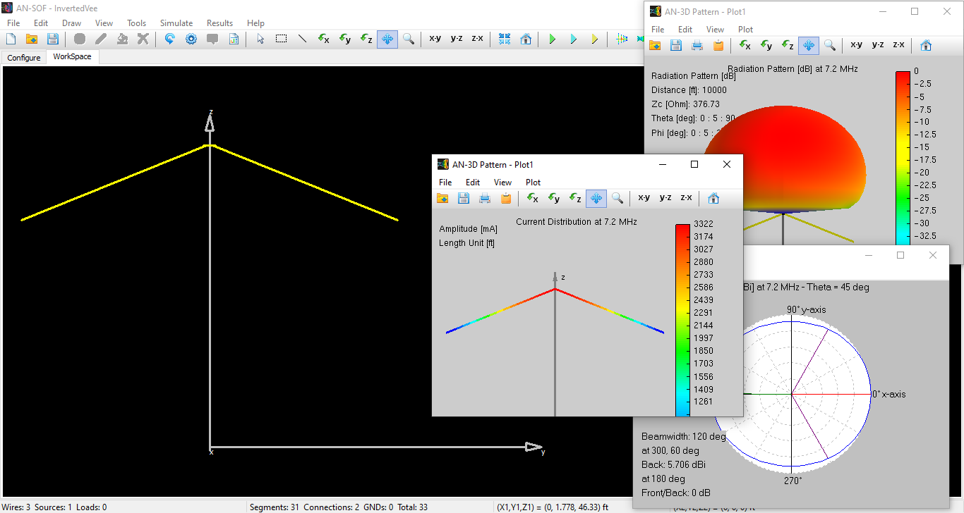
Feeding the antenna at the apex, where both legs meet at an acute angle, can be tricky in some simulation tools. In AN-SOF, a short horizontal wire is introduced at the vertex to bridge the two sloped legs (Fig. 1). This horizontal segment serves as the feedpoint, allowing a voltage source to be properly placed. This technique better reflects the physical feedpoint encountered in real installations.
To download the AN-SOF model, click the button located beneath Fig. 1.
Radiation Characteristics and Height Sensitivity
In free space, an inverted V closely resembles a half-wave dipole, producing a toroidal (donut-shaped) radiation pattern broadside to the wire. However, once ground effects are introduced, especially at HF frequencies, the picture changes dramatically.
For a dipole antenna with its apex at 50 feet (around 0.37λ at 7.2 MHz), the radiation pattern shows two primary lobes directed at 45 degrees from the zenith, perpendicular to the plane of the inverted V (Fig. 2).
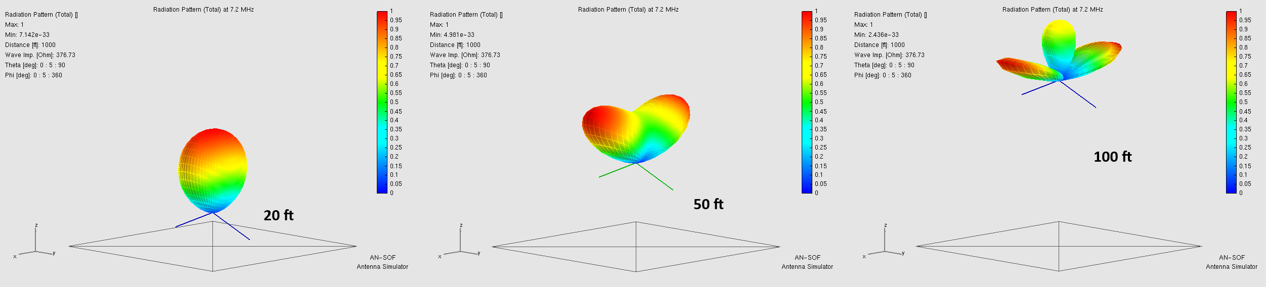
However, significantly lowering the apex, such as below 0.2λ, is generally undesirable for long-range communication as it results in increased ground losses and a shift in the radiation pattern. Specifically, the two main lobes merge into a single vertical lobe pointing upwards. Conversely, excessive height will introduce multiple secondary lobes in the radiation pattern.
AN-SOF allows antenna designers to explore these effects interactively. By adjusting the apex height, leg lengths, and slope angles, one can quickly assess trade-offs between impedance matching, radiation efficiency, and take-off angle. These capabilities are crucial for amateurs and professionals aiming to optimize their antennas for specific coverage goals.
Drawing the Inverted V in AN-SOF
Creating an inverted V in AN-SOF is straightforward using the “Start – Direction – Length” method for drawing wires. This approach lets you define each segment by its starting point, slope direction, and physical length. By entering the leg angles and length, the inverted V structure can be accurately modeled in 3D space.
The step-by-step process is shown in Figure 3, which also illustrates how a short wire can be added to connect the two antenna legs for voltage source excitation.
Conclusion
The inverted V is more than a space saving dipole; it’s a versatile antenna with performance characteristics highly dependent on geometry and ground interaction. Modeling it over real ground using tools like AN-SOF reveals important design considerations that aren’t obvious from simplified free space approximations. Whether you’re a ham radio enthusiast or a professional RF engineer, understanding the nuances of the inverted V can help you get the most out of your antenna system, on the 40 meter band and beyond.
