Search for answers or browse our Knowledge Base.
Guides | Models | Validation | Book
Automating 2-Element Quad Array Design: Scripting and Bulk Processing in AN-SOF
Struggling to design optimal 2-element quad arrays? This article explores automating the process using Scilab scripts and AN-SOF’s bulk processing. Generate & simulate multiple configurations with varying element spacing, saving time and uncovering potential performance improvements!

Two-element quad antennas are popular for their compact size and ability to achieve gain comparable to Yagi-Uda arrays with more elements. Additionally, quad antenna designs can be optimized for an input impedance near 50 Ohms at resonance, eliminating the need for an impedance matching network.
This article details modeling a 2-element quad array for the 10m band (28 MHz) using AN-SOF simulation software and Scilab scripting.
Advantages of Quad Antennas
Quad antennas offer several advantages, including:
- Simplicity: Their design is relatively simple to construct.
- Ease of Matching: They can be designed for a good impedance match at the operating frequency.
- Favorable Radiation Pattern: When the quad perimeter is around 1 wavelength or below, their radiation pattern resembles a half-wave dipole. This characteristic makes quad arrays just as quick to construct as dipole arrays.
Design Considerations
For near-resonant operation, the perimeter of a single quad should be roughly equal to one wavelength. In the case of a square loop, each side length would be a quarter-wavelength. To achieve a directional radiation pattern, the two quads in the array differ slightly in size. The driven element (connected to the source) is a square loop, while the reflector element (slightly larger in perimeter) is spaced 0.12 wavelengths behind it. For a more detailed explanation of a 5-element quad array design and the reasoning behind the perimeter requirement, refer to our article “Building a Beam: Modeling a 5-Element 2m Band Quad Array.”
Optimizing Element Spacing
Optimizing an antenna parameter involves finding the combination of other variables that achieves a desired outcome. In our case, we aim to maximize the antenna gain and front-to-back ratio by varying the spacing between the elements while keeping the quad size fixed.
AN-SOF Simulation with Bulk Processing
AN-SOF’s Run Bulk Simulation command allows for efficient simulations of multiple antenna configurations. This feature processes multiple files containing antenna descriptions in NEC format sequentially based on filename.
For our example, we will generate NEC files with varying element spacing for the 2-element quad antenna. The “Run Bulk Simulation” function will then be used to perform calculations for each file. Finally, we will analyze the generated CSV (Comma Separated Values) files to obtain the gain and front-to-back ratio based on element separation.
Scilab Scripting
We utilized Scilab, a free and open-source scientific computing software, to automate the process. Three scripts were created:
- NECcards.sce: This script defines generic functions corresponding to NEC commands for generating linear wires, defining the frequency, and other parameters. It should be executed first.
- 2-ElementQuad.sce: This script generates the NEC files based on the desired element spacing and should be run second.
- 2-ElementQuad_gain.sce: This script, executed last, plots the gain and front-to- back (F/B) ratio as a function of element spacing.
Results and Trade-offs
As demonstrated in the video below, maximizing gain and F/B ratio simultaneously is not possible. It’s generally preferable to choose the element spacing that maximizes the F/B ratio, as gain exhibits minimal variation within a reasonable range.
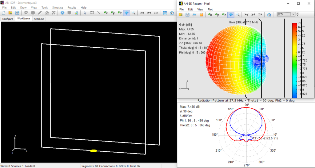
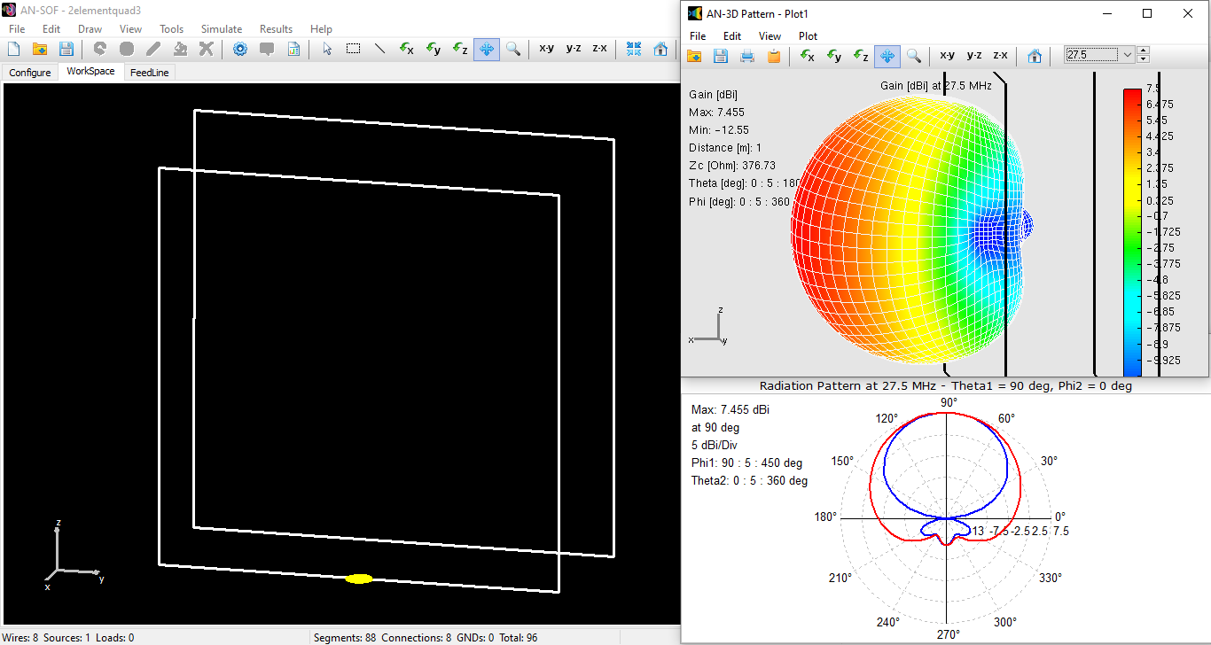
The image included depicts the antenna model in the AN-SOF workspace, the 3D radiation pattern showing gain in dBi, and the horizontal and vertical slices of the radiation pattern in a polar plot. This configuration, using only two elements and a compact size, achieves a gain of 7.5 dBi.

Conclusion
This article presented a method for modeling a 2-element quad array for the 10m band using AN-SOF and Scilab scripts. The approach allows for efficient exploration of different element spacing configurations to optimize the antenna’s front-to-back ratio while maintaining good gain characteristics. The downloadable scripts provide a foundation for those interested in further exploring quad antenna design and optimization techniques.

