Search for answers or browse our Knowledge Base.
Guides | Models | Validation | Book
Precision Modeling of Small Loop Antennas: Validating the Conformal Method of Moments (CMoM)
Validate the precision of the Conformal Method of Moments (CMoM) through this rigorous study of small loop antennas. By comparing simulated circular and square loops against classical asymptotic theory, we demonstrate how AN-SOF accurately models radiation resistance and directivity in the low-frequency limit, where antenna size is a tiny fraction of a wavelength. This article provides essential insights into shape-independence and numerical stability for electrically small radiator design.
Introduction to Small Loop Electromagnetics
Small loop antennas, defined as those where the total circumference is significantly smaller than the operating wavelength ($\lambda$), represent a fundamental class of radiators in radio frequency design. These antennas are characterized by a primarily inductive input impedance and a radiation resistance that is notoriously low, making them a challenge for both physical implementation and numerical simulation.
A critical theoretical prediction for these structures is that when the loop size tends toward zero, its radiation resistance, $R_{r}$, becomes independent of its geometric shape (e.g., circular vs. square) and depends solely on its physical area, $A$, measured in square wavelengths. This relationship is governed by the following asymptotic expression:
$\displaystyle R_{r} \,=\, 31200 \left( \frac{A}{\lambda^{2}} \right)^{2} \qquad (1)$
This equation assumes a uniform current distribution along the loop circumference, a condition typically met only when the loop is electrically “tiny”. Validating this behavior requires a simulation engine capable of handling extreme discretization challenges and curved geometries with high precision.
Advantages of the Conformal Method of Moments (CMoM)
The simulation results presented in this study were obtained using the Conformal Method of Moments (CMoM) implemented in the AN-SOF engine. Traditional Method of Moments (MoM) codes often rely on “staircase” approximations for curved structures, which can introduce artificial numerical noise, especially when calculating the very low radiation resistances typical of small loops.
The CMoM implementation provides two distinct advantages for this analysis:
- Geometric Fidelity: It allows for the exact modeling of curved antenna contours, eliminating the errors associated with linear segment approximations.
- Low-Frequency Stability: It remains numerically stable at extremely low frequencies, or equivalently, in scenarios where the antenna dimensions are a minute fraction of the wavelength.
Simulation Setup and Parameter Comparison
To demonstrate these capabilities, we compared two distinct geometries with an identical area of $0.01 \text{ m}^{2}$:
- Square Loop: $0.1\text{ m} \times 0.1\text{ m}$.
- Circular Loop: Radius of $0.05642\text{ m}$.
The loops were simulated across a frequency range of $20 \text{ MHz}$ to $200\text{ MHz}$. At $100 \text{ MHz}$ ($\lambda \approx 3 \text{ m}$), the normalized loop area is approximately $0.0011\lambda^{2}$, placing these structures firmly in the “small loop” category.
Input Resistance and Theoretical Departure
Figure 1 illustrates the computed input resistance for both the circular and square loops alongside the theoretical prediction from Equation (1).
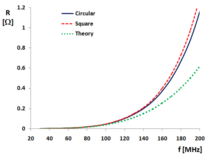
At lower frequencies (below $100 \text{ MHz}$), the simulation results for both shapes align perfectly with the theoretical curve, confirming that the radiation resistance is indeed independent of shape in the small-limit case. However, as the frequency increases toward $200 \text{ MHz}$, the theoretical prediction begins to depart from the simulation results. This divergence occurs because the assumption of a perfectly uniform current distribution and the validity of the simple asymptotic formula begin to fail as the loop circumference becomes a more significant fraction of the wavelength.
Directivity and Radiation Patterns
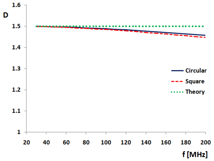
Another hallmark of small loop theory is that the peak directivity should be independent of both loop size and frequency, reaching a constant value of $1.5$ ($3/2$). This is identical to the directivity of a Hertzian dipole.
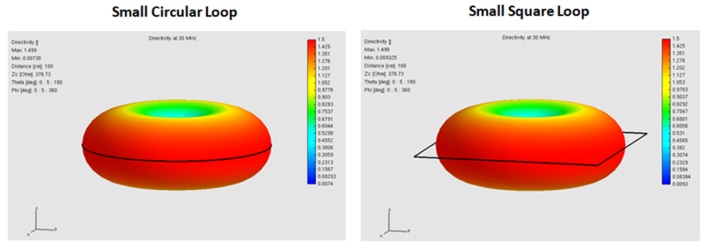
The AN-SOF simulation confirms this behavior across the sweep. Figure 2 shows the peak directivity remaining near the horizontal asymptote of $1.5$, with only slight variations occurring as the loops approach $200 \text{ MHz}$. The resulting radiation pattern is “donut-shaped,” with the nulls aligned along the axis of the loop, as shown in Fig. 3.

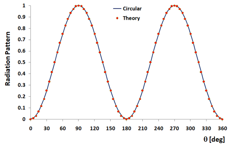
The mathematical expression for this directivity pattern is:
$\displaystyle D \,=\, \frac{3}{2} \; \sin^{2} \theta \qquad (2)$
where $\theta$ is the angle measured from the loop axis.
In Fig. 4, a vertical slice of the radiation pattern at $30 \text{ MHz}$ shows an almost perfect match between the circular loop simulation and the theoretical sine-squared distribution of Equation (2). The square loop results at this frequency are so closely aligned that they are indistinguishable to the naked eye, further validating the shape-independence of the far-field pattern in the small-loop limit.
Conclusion
The analysis of small circular and square loops serves as a powerful validation of the AN-SOF engine and its CMoM implementation. By accurately capturing the convergence of radiation resistance for different geometries at low frequencies, the simulation confirms the fundamental “area-only” dependence predicted by theory.
Furthermore, the stability of the 1.5 directivity value and the precision of the donut-shaped radiation patterns demonstrate that AN-SOF can handle the high-dynamic-range requirements of modeling electrically tiny antennas without falling victim to numerical instability. This benchmark provides antenna designers with the confidence that CMoM is a robust tool for designing not only large-scale arrays but also the compact, high-Q radiators utilized in specialized low-frequency and sensing applications.
See Also:
Technical Keywords: Small Loop Antenna, Radiation Resistance, Peak Directivity, Conformal Method of Moments (CMoM), AN-SOF Simulation, Low-Frequency Electromagnetics, Hertzian Dipole Pattern, Asymptotic Theory.
