Search for answers or browse our Knowledge Base.
Guides | Models | Validation | Book
Tabular Input of Linear Wires
Linear wires can be entered and edited in a table using the Tabular Input window. To access this feature, navigate to Draw > Tabular Input (Ctrl + T) in the main menu. This opens the Tabular Input window (see Fig. 1), which contains four tabs:
- Wires:
- Allows you to enter and edit linear wires by specifying their end coordinates, number of segments, wire radius, and materials.
- Sources:
- Enables you to connect sources to the wires listed in the Wires tab. A source must be connected to a specific wire segment.
- Loads:
- Allows you to connect loads to the wires listed in the Wires tab. A load must be connected to a specific wire segment.
- Trans. Lines:
- Enables you to connect transmission lines between two wire segments listed in the Wires tab.
Wires Tab
Select the Wires tab and enter values as specified in the column titles (see Fig. 1). Each row corresponds to a linear wire, and you can input details such as:
- Number of segments (Segs).
- Coordinates of the starting point (X1, Y1, Z1) and ending point (X2, Y2, Z2).
- Wire radius.
- Resistivity.
- Coating (dielectric insulation).
Note: Only wires with a circular cross-section can be entered.
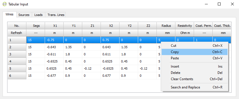
Table Interaction
- Right-click on the table to open a pop-up menu with standard options such as Cut (Ctrl + X), Copy (Ctrl + C), and Paste (Ctrl + V).
- Single cells can be selected by left-clicking on them or by using the TAB and arrow keys on the keyboard.
- Rows can be selected by clicking on the row number in the left column (No. column). Use the mouse or the up/down arrow keys to select a single row. The selected wire (row) is highlighted in red in the workspace. Double-click on a cell to exit row selection mode.
Row Operations
- Use Cut (Ctrl + X), Copy (Ctrl + C), and Paste (Ctrl + V) to manipulate selected rows.
- Use the Insert (Ins key) and Delete (Del key) options to add or remove rows.
- The Clear Contents (Ctrl + Del) option clears the content of a selected cell or row.
- The Search and Replace (Ctrl + R) option allows for bulk edits to wire end coordinates.
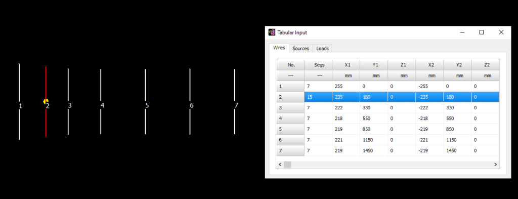
Wire Numbers in the Workspace
While the Tabular Input window is open, wire numbers are displayed in the workspace next to the corresponding wires (see Fig. 2). These numbers indicate the order of the wires in the table.
Note:
- Wires do not have permanent tags in AN-SOF. If a wire is deleted, the numbers will adjust automatically.
- Wire numbers are used solely for identification in the workspace while the Tabular Input window is open.
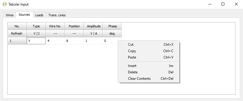
Sources Tab
Use the Sources tab to enter sources (see Fig. 3).
Entering Source Details
- Type Column: Enter “V” for a voltage source or “I” for a current source.
- Wire No. Column: Specify the wire on which the source is placed. Refer to the wire numbering in the No. column of the Wires tab.
- Position Column: Indicate the segment number where the source is connected. The segment number ranges from 1 to the number of segments (Segs) specified for the wire in the Wires tab.
- Amplitude Column: Enter the amplitude of the source in Volts or Amperes.
- Phase Column: Specify the phase of the source in degrees.
Table Interaction
- Right-click on the table to open a pop-up menu with standard options:
- Cut (Ctrl + X)
- Copy (Ctrl + C)
- Paste (Ctrl + V)
- Insert (Ins key)
- Delete (Del key)
- Clear Contents (Ctrl + Del)
These options function the same way as in the Wires tab, allowing you to manipulate cells and rows.
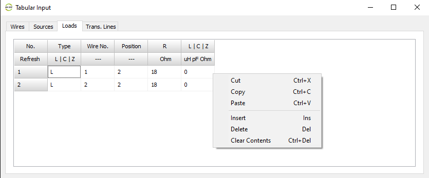
Loads Tab
Use the Loads tab to enter load impedances (see Fig. 4).
Entering Load Details
- Type Column: Enter one of the following:
- “L” for an inductor.
- “C” for a capacitor.
- “Z” for an impedance (R + jX).
- Wire No. Column: Specify the wire on which the load is placed. Refer to the wire numbering in the No. column of the Wires tab.
- Position Column: Indicate the segment number where the load is connected. The segment number ranges from 1 to the number of segments (Segs) specified for the wire in the Wires tab.
- R Column: Enter the resistance value (R) in Ohms.
- Last Column: Depending on the option entered in the Type column, input one of the following:
- Inductance (L) in the displayed unit.
- Capacitance (C) in the displayed unit.
- Reactance (X) in Ohms.
Table Interaction
- Right-click on the table to open a pop-up menu with standard options:
- Cut (Ctrl + X)
- Copy (Ctrl + C)
- Paste (Ctrl + V)
- Insert (Ins key)
- Delete (Del key)
- Clear Contents (Ctrl + Del)
These options function the same way as in the Wires tab, allowing you to manipulate cells and rows.
Trans. Lines Tab
Use the Trans. Lines tab to enter transmission lines and connect them to wire segments (see Fig. 5).
Entering Transmission Line Details
- Port 1 Columns:
- Specify the wire segment where Port 1 of the transmission line is connected by entering the Wire No. and Position. Refer to the numbering and number of segments specified for each wire in the Wires tab.
- Port 2 Columns:
- Similarly, specify the wire segment where Port 2 of the transmission line is connected by entering the Wire No. and Position.
- Additional Columns:
- Complete the Type, Z0 (characteristic impedance), VF (velocity factor), Length, and other columns as explained in the section Adding Transmission Lines.
- To simplify the process, select a row and double-click on an option in the right panel, which contains a collection of transmission line types with preloaded parameters.
Table Interaction
- Right-click on the table to open a pop-up menu with standard options:
- Cut (Ctrl + X)
- Copy (Ctrl + C)
- Paste (Ctrl + V)
- Insert (Ins key)
- Delete (Del key)
- Clear Contents (Ctrl + Del)
These options function the same way as in the Wires tab, allowing you to manipulate cells and rows.
Note:
- Entering a zero in Wire No., regardless of the Position entered, disconnects the port from the wire (putting the transmission line port in FREE status).
- Only transmission lines with both ports connected to wire segments will be considered in a simulation.
- Clicking on a row number (first column of the table) in the Trans. Lines tab highlights the transmission line in red in the AN-SOF workspace.
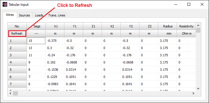
Refresh Button
A Refresh button is located just below the No. cell in all tabs of the Tabular Input window (see Fig. 6). Click the Refresh button to instantly apply changes. This eliminates the need to close and reopen the Tabular Input window to apply modifications.