Search for answers or browse our Knowledge Base.
Guides | Models | Validation | Book
The Exact Kernel
The kernel is the core of the integral equation that is solved in AN-SOF by means of the Method of Moments (MoM) to obtain the current distribution on metallic wires. Since the kernel cannot be calculated analytically in closed form, several approximations exist, among which the best known and widely used is the so-called thin-wire approximation.
The integral equation kernel is given by
$\displaystyle K(s,s’) = \frac{1}{4 \pi^2} \int_0^{2\pi} \int_0^{2\pi} G(\mathbf{r},\mathbf{r}’) \, d\phi’ d\phi \qquad (1)$
where $s$ and $s’$ are coordinates along a wire axis that represent an observation point and a source point, respectively. $G$ is the free space Green’s function, and $\phi$ and $\phi’$ are angles that determine points on the circumference of the wire cross-section. Thus, $\mathbf{r} = (s,\phi)$ represents an observation point on the wire surface, and $\mathbf{r}’ = (s’,\phi’)$ represents a source point. With that said, we can see that the kernel is obtained by averaging the Green’s function along the contour of the wire’s cross-section.
In the thin-wire approximation, the kernel is approximated as follows,
$\displaystyle K(s,s’) \approx \frac{e^{-j k R}}{4 \pi R}, \qquad R = \sqrt{|\mathbf{r}(s) \ – \ \mathbf{r}(s’)|^2 + a^2} \qquad (2)$
where $a$ is the wire radius, and $R$ is the distance between the source and observation points. When both points are on the same wire, the current will be represented by a filament on the wire axis, as the expression for $R$ shows. In particular, when both points coincide ($\mathbf{r} = \mathbf{r}’$), which happens when calculating the electromagnetic interaction of a wire with itself, the thin-wire kernel will vary as $1/a$, but the exact kernel will have an integrable singularity.
When a wire segment is thin, that is, its length is at least twice its diameter, the thin-wire approximation works well. However, as we increase the number of segments and therefore the segments get shorter, we will reach a threshold where the segments are too thick for the thin-wire approximation to work. This situation is particularly restrictive when we are investigating the convergence of some parameter or even when we want to fill the source gap at the antenna terminals using a short wire.
In AN-SOF, we have implemented the exact kernel instead of the thin-wire approximation. The solution involves separating the kernel into two terms: one containing an analytically integrable singularity, and the other containing a remainder that can be numerically integrated with minimal computational effort since it does not have any singularity. We have also provided the option of using an “extended kernel,” similar to the one used in NEC (Numerical Electromagnetics Code), where a series expansion of the kernel in terms of the wire radius is utilized, and the $a^2$ and $a^4$ terms are retained.
Note
In summary, it should be noted that AN-SOF implements both the Exact Kernel and the Extended Kernel, while NEC uses an extended kernel and the thin-wire approximation.
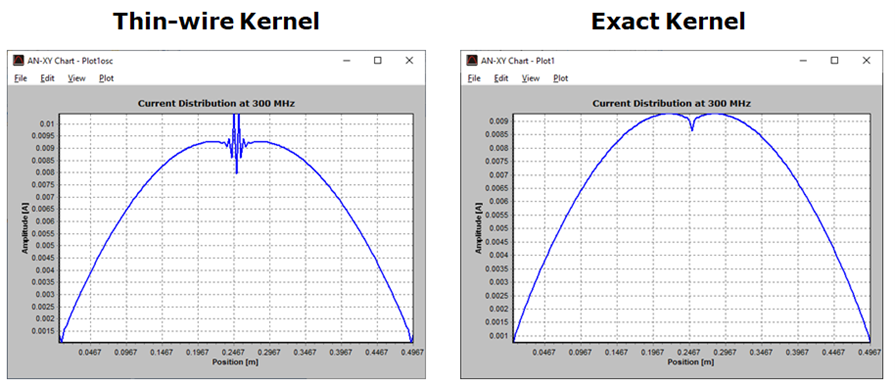
Fig. 1 shows the current distribution in amplitude along a center-fed half-wave dipole obtained using both the thin-wire approximation and the exact kernel. The antenna has been divided into segments with a diameter three times greater than their lengths, resulting in very thick wire segments in this case.

The thin-wire kernel exhibits the well-known oscillatory effect on the current distribution near the position of discrete sources and at wire ends for a segment diameter-to-length ratio greater than 1. As we can see, these oscillations disappear when the exact kernel is used instead of the thin-wire approximation.
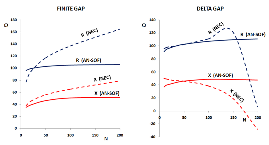
The effect of not using the exact kernel can also be observed in the lack of convergence of the input impedance when the number of segments increases, as shown in Fig. 2 for the AN-SOF vs. NEC-2 results.

Note
In conclusion, we will achieve the highest possible accuracy in the calculation of the current distribution and antenna input impedance by using the Exact Kernel.
