Search for answers or browse our Knowledge Base.
Guides | Models | Validation | Book
The 17m Band 2-Element Delta Loop Beam: A Compact, High-Gain Antenna for DX Enthusiasts
Conquer the 17-meter band with the 2-element Delta Loop Beam antenna. This compact, high-gain design boasts near-perfect impedance matching, making it perfect for DX enthusiasts. Download the AN-SOF model and unlock its potential!
The 17-meter band presents a unique set of design challenges for radio antenna designers targeting DX applications. Achieving high directivity while maintaining portability and ease of deployment requires careful consideration. This article presents a 2-element Delta Loop Beam antenna that addresses these challenges head-on. The antenna boasts a compact form factor, exceptional gain, and near-perfect impedance matching, making it an ideal choice for DX enthusiasts.
Minimalist Design, Maximum Performance
The design philosophy behind this antenna is one of elegant simplicity. It represents the minimum viable configuration for a directional Delta Loop array, consisting of just two elements: a driven element at the front (where the feed line connects) and a passive reflector element behind, reminiscent of the Yagi-Uda architecture. Both elements are equilateral triangles with perimeters of approximately one wavelength on the 17-meter band. To achieve optimal forward directivity, the driven element is deliberately crafted slightly smaller than the reflector. The element spacing is tuned to 0.12 wavelengths, ensuring optimal performance.
Impedance Harmony: Eliminating Matching Networks
With these carefully chosen dimensions, the array exhibits an almost purely resistive input impedance of approximately 50 Ohms. This remarkable characteristic eliminates the need for an additional impedance matching network, simplifying construction. This feature is particularly advantageous for portable DX applications.

Visualizing Performance: The Power of Modeling
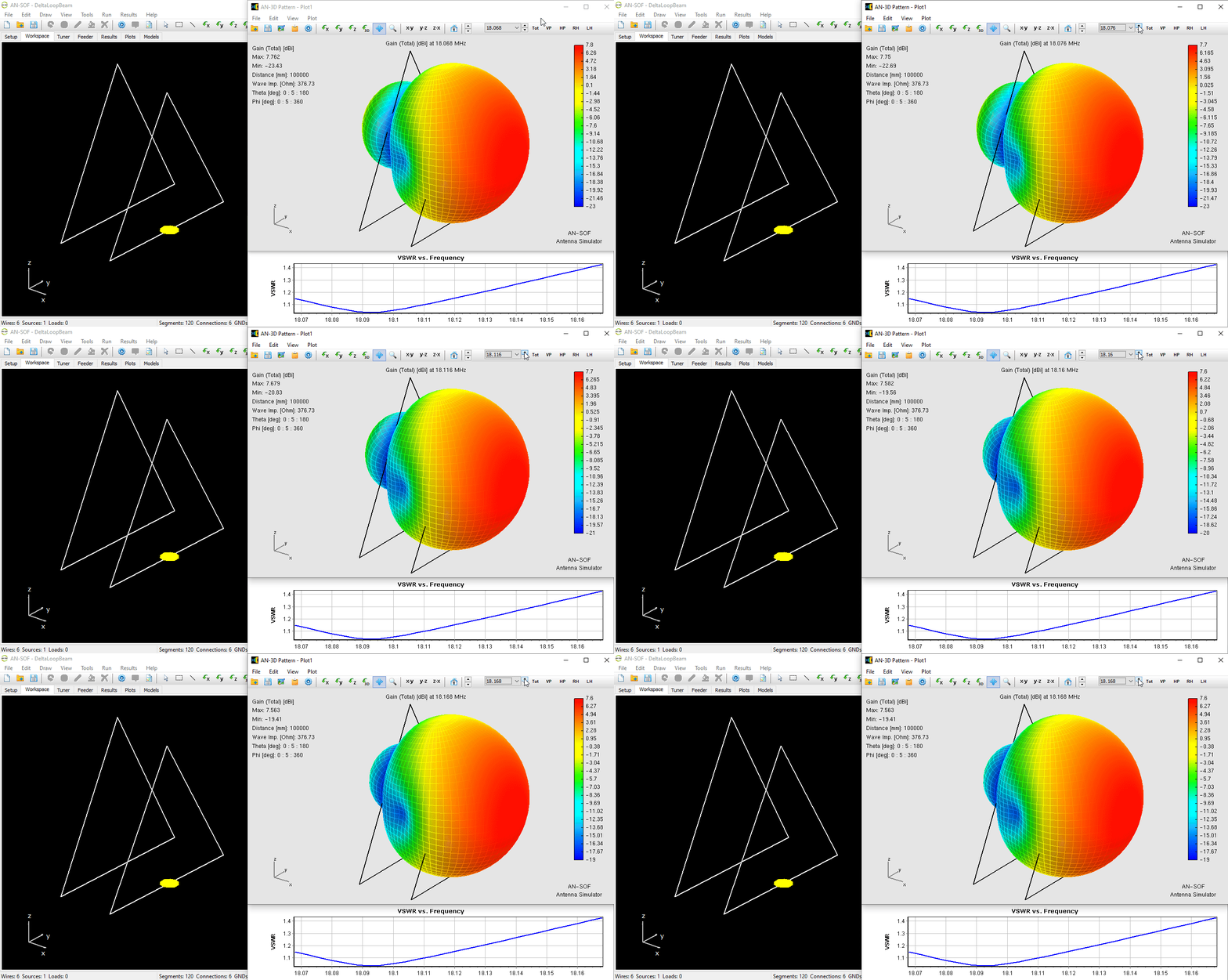
The figure above showcases the Delta Loop Beam model within the AN-SOF simulation workspace. It depicts the antenna geometry, its radiation pattern, and the VSWR across a range of frequencies. The radiation pattern, plotted in dBi, reveals a peak gain of 7.7 dBi. The animation demonstrates how the radiation lobes dynamically change with frequency. Notably, the VSWR remains below 2 throughout the analyzed frequency range, indicating excellent impedance matching across the band.
Modeling with Confidence: Capturing Sharp Angles
To accurately capture the acute angles of the Delta Loops, it is recommended to activate the Exact Kernel option within AN-SOF’s Setup window. This ensures accurate results even for intricate geometries, guaranteeing reliable simulation data.
Beyond Theory: Exploring Real-World Scenarios
While the model depicts the antenna in an ideal free-space environment, real-world deployments often involve ground planes and environmental factors. We encourage you to download the AN-SOF model (button below the figure) and delve into how the antenna behaves when incorporating realistic ground planes into the simulation. AN-SOF conveniently provides a library of soil constants (conductivity and permittivity) to facilitate this research.
Feel empowered to experiment! Resize the antenna, tweak the element spacing, and observe how these adjustments affect gain and resonant frequency. You might discover the perfect configuration for your specific DX needs, whether it be maximizing gain for weak signal reception or fine-tuning the resonant frequency for a particular contest.
And for those interested in the intricacies of EMF compliance and RF exposure regulations, this Delta Loop Beam model has been featured as a case study in our recent article, “Evaluating EMF Compliance – Part 1: A Guide to Far-Field RF Exposure Assessments.” Dive into the details and gain valuable insights into ensuring safe and responsible antenna deployment.

