Search for answers or browse our Knowledge Base.
Guides | Models | Validation | Book
Can AI Design Antennas? Lessons from a 3-Iteration Yagi-Uda Experiment
Can AI really design antennas? We put it to the test, transforming chatbot suggestions into a working 3-element Yagi-Uda. Discover how AI accelerates design, where it stumbles, and why your expertise still makes the difference.

Harnessing AI for Efficient Antenna Design: A Yagi-Uda Case Study
Since the advent of AI-powered chatbots, we have gained a powerful tool to streamline and refine antenna design procedures. This article demonstrates how AI chatbots can assist in modeling and designing a 3-element Yagi-Uda antenna array, though the methodology can be extended to other antennas of similar complexity.
Rather than requesting a complete antenna design in a single prompt, we adopt an iterative approach: starting with a broad query and progressively refining the scope with additional details. Through extensive testing, we found this method far more effective than attempting to generate a fully optimized design in one step.
The proposed workflow involves:
- Providing a structured input, a .txt file containing NEC commands supported by AN-SOF Antenna Simulator.
- Instructing the AI to generate corresponding NEC code based on the antenna’s geometry, frequency, and environmental parameters.
This approach is particularly beneficial for:
- Beginners who struggle with manually defining Cartesian coordinates (x,y,z) for wire ends.
- Experienced designers seeking a rapid prototyping tool, as the AI-generated code can serve as a baseline for further optimization.
In the following sections, we detail this process using a 3-element Yagi-Uda array as an example, with ChatGPT as the AI platform due to its widespread adoption. The principles, however, apply universally to other antenna types and AI chatbots.
Integrating NEC Code into AN-SOF: Legacy Support for Modern Antenna Design
The Numerical Electromagnetics Code (NEC) was developed in the 1970s by researchers at Lawrence Livermore National Laboratory, with its first public release (NEC-2) built upon older FORTRAN-based codes. Designed for the computational constraints of its era, limited memory, processing power, and punch-card input systems, NEC carries inherent limitations in its architecture. The final version, NEC-5, is now unsupported. Nevertheless, the NEC format has become the de facto standard for wire antenna modeling, owing to its decades of widespread use and the vast library of existing antenna models created in this format.
To preserve compatibility with this legacy ecosystem, AN-SOF includes a dedicated .nec file importer, allowing users to leverage existing NEC-format antenna models without redundant rework. However, nuances exist:
- Punch-Card Legacy – NEC commands often include unused fields (requiring zero-placeholders) due to their punch-card origins.
- AN-SOF’s Adaptations – While AN-SOF supports nearly all NEC commands, minor syntax differences may require adjustments. (Refer to: Importing Wires for specifics.)
AI as a NEC Code Generator
The key innovation lies in using AI chatbots to bridge colloquial design descriptions with NEC-compatible output. Instead of manually writing .nec files, users can:
- Describe the antenna’s geometry, frequency, and environment in plain language.
- Direct the AI to generate .nec code adhering to AN-SOF’s supported command set.
This approach bypasses the tedious process of manual coordinate entry while maintaining compatibility with AN-SOF’s importer, ideal for both rapid prototyping and educational use.
Step-by-Step AI Workflow for NEC Code Generation
Phase 1: Broad Initial Inquiry
We begin with a general question to establish baseline parameters. For our Yagi-Uda example:
Prompt:
What are the recommended element lengths and spacings for a Yagi-Uda antenna?
This intentionally vague query allows the AI to provide foundational knowledge without constraints.
Phase 2: Targeted Parameter Refinement
Next, we narrow the scope by specifying:
- Number of elements
- Target frequency band
Refined Prompt:
Could you please recommend the element lengths and spacings for a 3-element Yagi-Uda antenna for the 10m band?
Key Observations:
- Polite phrasing (“please”) demonstrably improves response quality
- For simplicity, we omit:
- Element thickness (affects feedpoint impedance and bandwidth)
- Ground plane considerations
- Free-space modeling assumed
- Wire radius will be AI-suggested (can be refined in subsequent iterations)
Phase 3: NEC Code Generation with AN-SOF Constraints
The critical technical phase involves:
- Attaching the reference file “AN-SOF_Commands.txt” (Download here)
- Providing strict formatting instructions:
Final Prompt:
AN-SOF Antenna Simulator supports importing NEC-format files with modified command syntax (see attached reference). Please generate a NEC input file for: a 3-element Yagi-Uda antenna for the 10m band in free space.
Requirements:
- No empty lines
- CM cards only at file start (no interleaved comments)
- Exclude:
- CE (comment termination)
- RP (radiation pattern – AN-SOF handles this separately)
- Provide raw code only (no explanatory text)
Rationale for Constraints:
- AN-SOF automatically calculates 3D patterns at 5° resolution (adjustable)
- Eliminating explanations streamlines copy-paste workflow
AI-Generated Results and Simulation Validation
Phase 1: Baseline Design Parameters
ChatGPT Response to Initial Prompt:
The recommended element lengths and spacings for a Yagi-Uda antenna depend on the operating frequency, the number of elements, and the desired performance characteristics (e.g., gain, front-to-back ratio). Below are general guidelines for a 3-element Yagi-Uda antenna, which consists of a reflector, driven element, and director:
Element Lengths:
- Reflector: 1.05λ/2 (5% longer than the driven element)
- Driven Element: 0.95λ/2 to 0.98λ/2 (typically close to 0.98λ/2 for impedance matching)
- Director: 0.90λ/2 to 0.95λ/2 (5–10% shorter than the driven element)
Where λ is the wavelength.
Element Spacings:
- Reflector to Driven Element: 0.15λ to 0.25λ (typically around 0.20λ)
- Driven Element to Director: 0.1λ to 0.20λ (typically around 0.15λ)
General Guidelines for More Elements:
For higher-gain Yagi antennas with additional directors:
- Add more directors (each about 0.90λ/2 to 0.95λ/2)
- Spacing between directors: 0.15λ to 0.25λ, increasing slightly toward the end for impedance matching.
Phase 2: Band-Specific Optimization (10m Band)
Refined Prompt Response (28.5 MHz Center Frequency):
For a 3-element Yagi-Uda antenna designed for the 10-meter band (28–29.7 MHz), the recommended element lengths and spacings are as follows:
Design Parameters:
- Center frequency: 28.5 MHz (mid-band)
- Wavelength (λ):
λ = 299,792,458 m/s / (28.5 × 10⁶ Hz) ≈ 10.52 m
Recommended Element Lengths:
- Reflector: 1.05λ/2 → ≈ 5.52 m
- Driven Element: 0.98λ/2 → ≈ 5.17 m
- Director: 0.90λ/2 → ≈ 4.74 m
Recommended Element Spacings:
- Reflector to Driven Element: ≈ 2.05 m (≈ 0.20λ)
- Driven Element to Director: ≈ 1.57 m (≈ 0.15λ)
Phase 3: NEC Code Generation & Initial Simulation
AI-Generated NEC Code (First Attempt):
Here is the NEC input file for a 3-element Yagi-Uda antenna designed for the 10 m band (28.5 MHz) in free space, following AN-SOF’s supported command cards:
CM 3-Element Yagi-Uda Antenna for 10m Band
CM Designed for 28.5 MHz in Free Space
CM Lengths and wire radii in meters
GW 1 11 -2.76 0 0 2.76 0 0 0.005
GW 2 11 -2.59 0 0 2.59 0 0 0.005
GW 3 11 -2.37 0 0 2.37 0 0 0.005
GE 0
FR 0 1 0 0 28.5 0
EX 0 2 6 0 1 0
EN
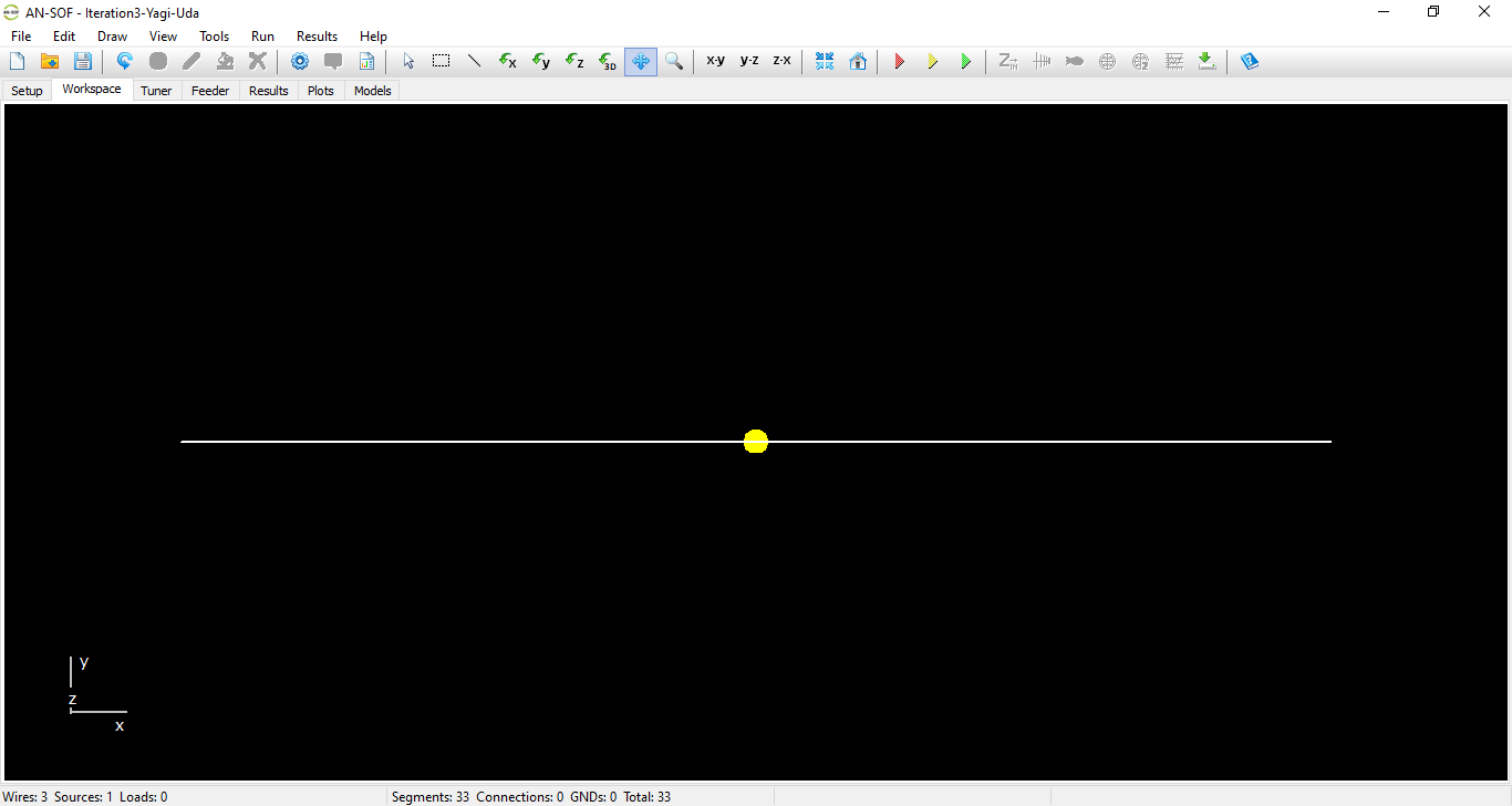
The responses to the first two prompts provided correct theoretical parameters for the Yagi-Uda design. To implement this, we copy the AI-generated NEC code and paste it into a text editor such as Notepad, saving the file with a .nec extension. This file is then imported into AN-SOF through the File menu > Import Wires > NEC format option. Upon initial import, we observe all three elements incorrectly superimposed at the same coordinates, as shown in Figure 1.

This error demonstrates the current limitations of AI as an assistant rather than a fully autonomous design tool. To correct this, we provide feedback to the AI, specifically noting the lack of proper spacing between elements along the boom axis. The AI acknowledges this oversight and responds with corrected NEC code featuring proper Y-axis spacing between elements:
You’re right! The elements need to be properly spaced along the boom axis (Y-axis). Below is the corrected NEC input file with the correct element spacings:
CM 3-Element Yagi-Uda Antenna for 10m Band
CM Designed for 28.5 MHz in Free Space
CM Lengths and wire radii in meters
GW 1 11 -2.76 0 0 2.76 0 0 0.005
GW 2 11 -2.59 2.05 0 2.59 2.05 0 0.005
GW 3 11 -2.37 3.62 0 2.37 3.62 0 0.005
GE 0
FR 0 1 0 0 28.5 0
EX 0 2 6 0 1 0
EN
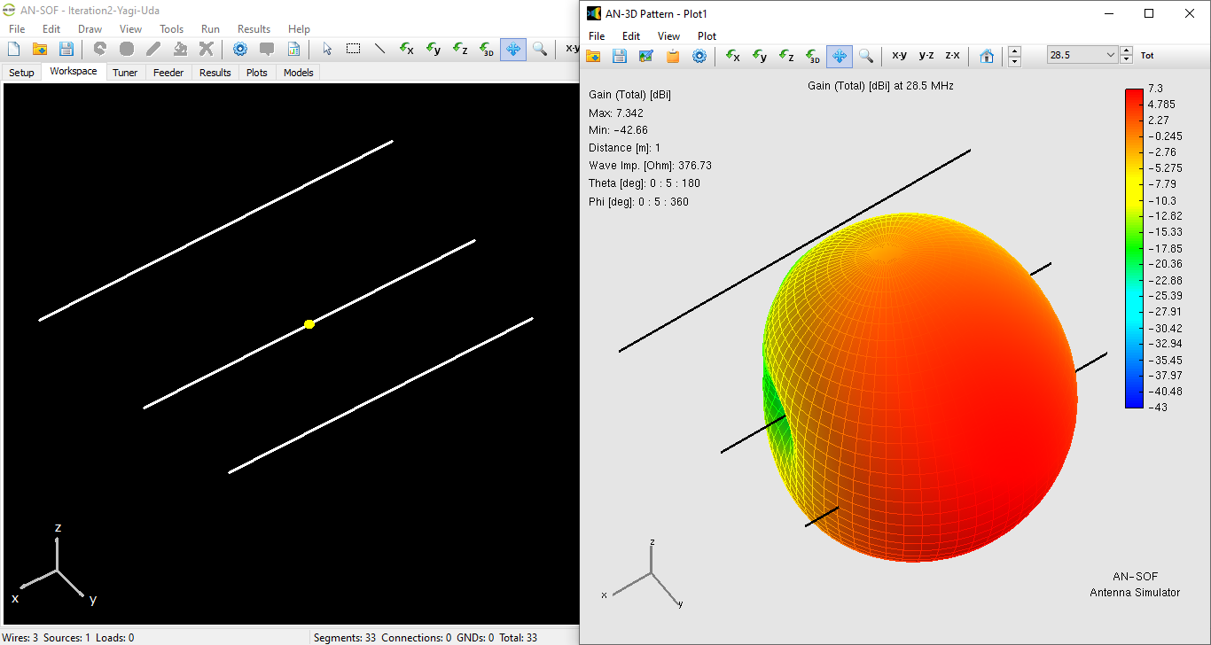
After importing this revised file, we successfully obtain a properly spaced 3-element Yagi-Uda array. Subsequent simulation yields the results displayed in Figure 2, confirming the corrected antenna geometry.

Impedance Refinement
The initial design yielded acceptable performance with a feedpoint impedance of 44 + j 11 Ω (VSWR = 1.3) and a gain of 7.3 dBi. While easily matchable to 50 Ω systems, we sought to improve the resonance characteristics through AI-assisted optimization.
When instructed to optimize for resonance, the AI generated revised NEC code that modified both the driven element length and inter-element spacings. The adjusted parameters shifted the feedpoint impedance closer to resonance while maintaining the antenna’s radiation characteristics. Below is the AI-generated NEC code implementing these changes:
CM 3-Element Yagi-Uda Antenna for 10m Band
CM Designed for 28.5 MHz in Free Space
CM Impedance Optimized for 50 Ohms
GW 1 11 -2.76 0 0 2.76 0 0 0.005
GW 2 11 -2.55 2.15 0 2.55 2.15 0 0.005
GW 3 11 -2.37 3.72 0 2.37 3.72 0 0.005
GE 0
FR 0 1 0 0 28.5 0
EX 0 2 6 0 1 0
EN
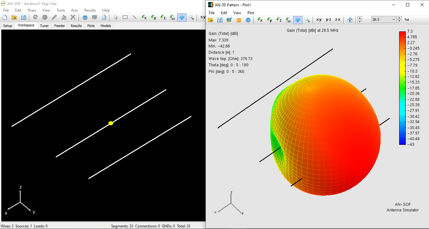
The optimized version demonstrated:
- Refined Impedance: 42 − j 4.9 Ω (VSWR = 1.2)
- Consistent Gain: 7.3 dBi (Fig. 3)

Wire Radius Optimization
The AI’s initial solution specified a 5 mm wire radius, a dimension requiring careful evaluation due to its significant impact on antenna performance. Conductor thickness critically influences two fundamental characteristics: (1) feedpoint impedance matching and (2) operational bandwidth. For physical implementations, this simulated parameter must align with available construction materials (e.g., tubing or wire gauges). Implementing such changes demands an iterative design approach, as each adjustment to conductor diameter produces coupled effects on both impedance and bandwidth that may require compensatory tuning of other parameters.
Segment Density: Balancing Accuracy and Efficiency
The AI-generated NEC code specifies 11 segments per element, the minimum recommended value for basic simulations. This configuration is valid for initial modeling because the odd segment count ensures proper source placement at the center of the driven element while keeping computational demands low.
However, practical experience shows that higher segment density is often required for accurate results. Convergence analyses and comparisons with measured data indicate that approximately 50 segments per element are typically needed to reliably predict VSWR versus frequency performance. This increased density better accounts for:
- Current distribution along the elements
- End effects at wire terminations
- Mutual coupling between closely spaced elements
For optimal workflow efficiency, we recommend beginning with the AI’s 11-segment model for initial prototyping, then performing convergence testing with progressively higher segment counts (e.g., 25, 51) when refining the design. The final segment count should be determined based on the required accuracy, particularly for bandwidth-sensitive applications or when correlating simulations with physical measurements.
Conclusions: AI as a Collaborative Design Tool
This case study demonstrates that AI chatbots can serve as valuable assistants in antenna design, particularly for generating initial models and optimizing parameters. However, the process requires active human guidance to identify and correct errors, ensuring the final design meets specifications.
In our 3-element Yagi-Uda example, the AI provided a functional starting point but required three iterations to achieve optimal results:
- Initial NEC code generation (superimposed elements, corrected via feedback)
- Proper spacing implementation (validated through simulation)
- Impedance refinement (fine-tuned for better resonance)
Key observations:
- AI accelerates design workflows by rapidly generating NEC code from natural language descriptions.
- Human oversight remains essential to verify geometry, spacing, and electrical characteristics.
- Iterative refinement yields better results than expecting perfect output in a single prompt.
While current AI cannot replace an experienced antenna designer, it serves as a powerful co-pilot, reducing manual calculations and offering intelligent suggestions. Future improvements in AI reasoning may further enhance its utility, but for now, guided collaboration produces the most reliable results.
Final Thought:
“AI generates the blueprint, human insight transforms it into a working design.”

