Search for answers or browse our Knowledge Base.
Guides | Models | Validation | Book
Advantages of AN-SOF for Simulating 433 MHz Spring Helical Antennas for ISM & LoRa Applications
Accurate antenna simulation is crucial for designing high-performance antennas for various applications, including ISM and LoRa. AN-SOF software offers significant advantages over traditional methods for simulating 433 MHz spring helical antennas, enabling designers to achieve optimal antenna performance.
Challenges of Modeling Helical Antennas with Traditional Methods
Traditional antenna simulation techniques, such as the Numerical Electromagnetics Code (NEC), often encounter limitations when modeling helical antennas. These limitations stem from the inherent assumptions made in the integral equation’s kernel, such as the thin-wire approximation. This approximation breaks down for small, compact helical antennas with their complex geometries of closely spaced, curved, and thick wires.
Advantages of AN-SOF for Helical Antenna Simulation
AN-SOF overcomes the limitations of traditional methods by employing a more robust and versatile approach with an exact kernel formulation. Here’s how AN-SOF benefits antenna designers:
- Accurate Modeling of Complex Geometries: AN-SOF eliminates the need for simplifications by accurately modeling the complex geometry of spring helical antennas, including tight bends, thick wires, and curved sections. This ensures accurate current distribution and radiation patterns.
- Superior Handling of Curved Wires: AN-SOF is adept at handling curved wires, a key characteristic of helical antennas, by employing the Conformal Method of Moments (CMoM). This ensures that the current distribution and radiation patterns are precisely simulated.
- Precise Simulation of Closely Spaced Wires: The tight coil spacing in the 433 MHz compact helical antennas can be accurately modeled by AN-SOF. This capability is essential for capturing the electrical interactions between the antenna windings, which significantly affect its performance.
- Modeling of Short Segments: AN-SOF can effectively represent the short curved segments that must be used in helical antenna models. This characteristic is crucial for simulating the antenna’s resonant behavior and input impedance.
Case Study: Using AN-SOF for 433 MHz Helical Antenna Simulation
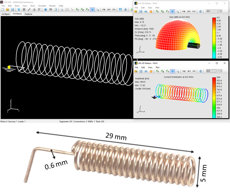
Consider a 433 MHz spring helical antenna designed for LoRa applications, as specified in the datasheet available here. This antenna is physically short compared to the wavelength (around 4-5% in this case). Consequently, its inherent radiation resistance is low. The helical turns compensate for this by effectively increasing the electrical length of the antenna, boosting radiation resistance to usable values. AN-SOF software is particularly adept at simulating such antennas due to its ability to handle complex geometries. This allows for accurate modeling of the electrical behavior, including input impedance, radiation pattern, and gain.
An important aspect to consider during the simulation is the inclusion of a ground plane below the antenna. In real-world applications, helical antennas typically operate over a ground plane or with a nearby PCB, which influences their performance. By incorporating a ground plane in the AN-SOF simulation, designers can obtain results that closely match the actual antenna’s behavior, including its input impedance and gain values specified in the datasheet.
The impact of the ground plane can be illustrated by considering the example shown below. Here, a perfect ground plane is used in the AN-SOF simulation, resulting in an input impedance of 48 Ohms, very close to the 50 Ohms specified in the antenna’s datasheet. This close match highlights the importance of including a ground plane for accurate simulations.

The gain simulated with the ground plane is higher compared to the gain the antenna would achieve in free space (without any surrounding objects). This difference is of 3 dB in this example. To estimate the antenna’s performance in free space, we can subtract 3 dB from the simulated gain, resulting in a free-space gain of 1.8 dBi. This value is closer to what might be specified in the datasheet, which typically refers to free-space performance. While this is a simplified model, it demonstrates AN-SOF’s ability to capture the real-world influence of the environment on antenna performance.
Conclusion
AN-SOF software offers distinct advantages for simulating 433 MHz spring helical antennas for ISM and LoRa applications. Its ability to handle complex geometries, closely spaced wires, and short curved segments makes it a powerful tool for achieving accurate antenna design. Additionally, incorporating a ground plane in the simulation is essential for obtaining realistic results that match the antenna’s datasheet specifications.
By leveraging AN-SOF’s capabilities, antenna designers can optimize the performance of their helical antennas, leading to successful implementations in various wireless applications.

