Search for answers or browse our Knowledge Base.
Guides | Models | Validation | Book
The MI2 Fractal Loop: Achieving Resonant Efficiency in Compact Apertures
Discover the power of space-filling curves through this analysis of the MI2 Fractal Loop antenna. Modeled in AN-SOF, this HF ‘Snowflake Quad’ achieves a resonant resistance and a 2 dBi gain. Learn how fractal iterations enable significant size reduction in HF antennas without the efficiency losses typical of standard small loops.
Introduction to Fractal Electromagnetics
Fractal antennas represent a revolutionary shift from Euclidean geometry to self-similar, space-filling structures. In the realm of Computational Electromagnetics (CEM), fractals such as the Minkowski and Koch curves allow an antenna to possess a large electrical length ($L_{elec}$) within a small physical volume ($V$).
The primary benefit of the fractal loop, often called the “Snowflake Quad,” is that it overcomes the limitations of the “Small Loop Approximation.” Traditional small loops suffer from extremely low radiation resistance ($R_r$) and poor efficiency. Fractal iterations increase the perimeter length and the complexity of the current distribution, which in turn raises the resonant resistance to levels compatible with standard feedlines.
The MI2 Model: Design and Origin
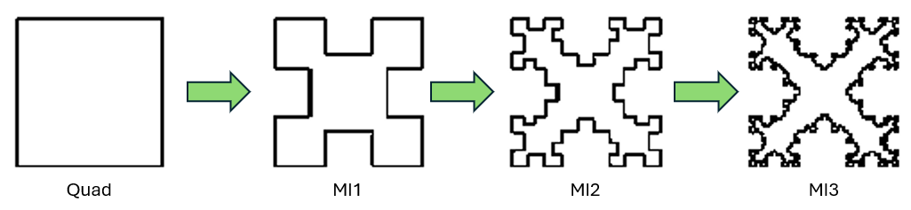
Dr. Nathan Cohen popularized the MI2 Fractal Loop, as documented in his paper with Hohlfeld, titled “Fractal Loops and the Small Loop Approximation” (Communications Quarterly, 6, 77-81, 1996). The “MI2” designation refers to the second iteration of a Minkowski fractal generator applied to the four sides of a standard square loop (Fig. 1).
Model Specifications in AN-SOF:
- Operating Frequencies: $15.25-15.45 \text{ MHz}$ (HF Band)
- Physical Footprint: $2.8 \times 2.662 \text{ meters}$
- Total Wire Length: $27.564 \text{ meters}$
- Structure: Iterated Minkowski segments modeled using AN-SOF’s Conformal Method of Moments (CMoM).
One of the challenges in simulating fractal structures is the high number of segments required to accurately capture the sharp bends and self-similar sub-structures. Using our CMoM solver, we can ensure that the current continuity at these fractal junctions is maintained with higher precision than standard piecewise-linear MoM codes.
Simulation Results and Validation
Our AN-SOF simulation aimed to replicate the findings reported in “Fractal Loops and the Small Loop Approximation,” Cohen, N.L., and Hohlfeld, R.G., Communications Quarterly, 6, 77-81, 1996. The results show a remarkable correlation between classic theory and modern CEM simulation.
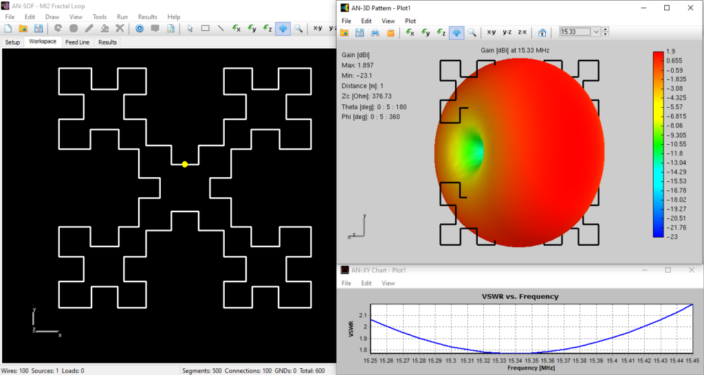
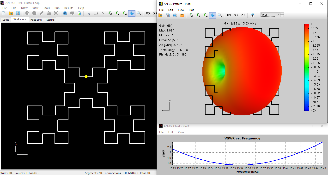
- Resonance and Impedance: The first resonance occurs at $15.335 \text{ MHz}$. At this point, the input resistance is $28\, \Omega$. This is a significant improvement over a standard small loop of similar outer dimensions, providing a much easier path for impedance matching to $50\, \Omega$ coax.
- Gain: The calculated gain is $1.90\text{ dBi}$, which is almost identical to the $2\text{ dBi}$ reported by Cohen. This confirms that the fractal geometry does not sacrifice the fundamental gain of a loop while shrinking its size.
- Bandwidth: The $2:1/50\,\Omega$ VSWR bandwidth is $1.04\%$. This narrow bandwidth is a characteristic trade-off for high-$Q$ compact antennas, necessitating precise construction.
Figure 2 shows the MI2 fractal loop model in the AN-SOF workspace, the calculated 3D gain pattern in dBi, and the VSWR curve versus frequency. The radiation pattern has the typical donut shape expected for a small loop antenna. The model can be downloaded by clicking the button below the figure.
Conclusions
The MI2 Fractal Loop serves as a masterclass in the trade-offs of antenna miniaturization. By utilizing the MI2 Minkowski iteration, we have successfully reduced the physical aperture while maintaining a resonant resistance ($28\, \Omega$) that is usable in real-world HF applications.
The high degree of agreement between our AN-SOF model and the original Cohen/Hohlfeld report ($1.90\text{ dBi}$ vs $2\text{ dBi}$) validates our solver’s ability to handle complex, space-filling geometries. For antenna designers looking to increase gain and directivity further, this single element serves as the building block for arrays of snowflake quads.
See Also:
Technical Keywords: Fractal Antenna, MI2 Minkowski Loop, Snowflake Quad, Compact Antennas, Conformal MoM, Resonance, HF Antenna.
