Search for answers or browse our Knowledge Base.
Guides | Models | Validation | Book
Modeling Common-Mode Currents in Coaxial Cables: A Hybrid Approach
This article presents a hybrid modeling approach for coaxial transmission line antenna feeders, focusing on the impact of common-mode currents on the antenna radiation pattern. By explicitly modeling the outer shield of coaxial cables, we can accurately predict and mitigate RF interference, enhancing antenna system performance for RF engineers and enthusiasts.

Introduction
In the realm of antenna engineering, the impact of common-mode currents on coaxial cable feeders is a crucial factor to consider. These currents can cause unintended radiation, potentially leading to RF interference in nearby equipment and reducing the overall performance of the antenna system. Understanding and mitigating these effects are essential for achieving optimal antenna performance, especially in applications involving precise and sensitive RF measurements.
Hybrid Modeling of Coaxial Transmission Line
To accurately model the behavior of coaxial cables used in antenna systems, this study presents a hybrid approach. The antenna model discussed here comprises a resonant dipole nearly half a wavelength long, positioned horizontally at a height of half a wavelength above a lossy ground plane. It is centrally fed through a 50 Ohm transmission line, representing a coaxial cable connected to a voltage source near ground level.
As sources must always be connected to wire segments, a very short wire (just 0.3% of the wavelength) having one segment supporting the source has been added near the ground plane. The frequency is set to 14 MHz in the simulation just as an example, since the purpose is to describe the model conceptually.

While the initial model includes the source, transmission line, and dipole, an additional vertical wire has been integrated to represent the outer surface of the coaxial cable shield. This addition exemplifies a hybrid model of the coaxial transmission line: the interior of the line is implicitly modeled, as it does not radiate, while the exterior of the shield is explicitly represented by a metallic wire with a diameter matching that of the cable shield. This approach allows for the accurate representation of the radiation effect of the common-mode current flowing on the exterior of the coaxial cable shield, which may cause RF interference in the vicinity of the antenna.
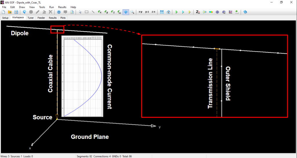
By applying an input power of 100 W and plotting the common-mode current in the vertical wire, the current’s peak value of 127 mA is observed in the middle of the wire, following a nearly sinusoidal pattern, as expected for a half-wave wire. Figure 1 shows the antenna model in AN-SOF’s workspace on the left, where the current distribution along the coax shield is plotted. The inset on the right provides a zoomed-in view of the horizontal dipole center, showcasing the transmission line model and the wire representing the coax shield, both connected to the dipole center. The maximum current at the dipole center is 1.12 A for an input power of 100 W at the source. Therefore, the common-mode current is on the order of 10% of the current on the dipole.
The detailed procedure to model the coaxial cable in AN-SOF can be found at this link: Modeling Coaxial Cables.

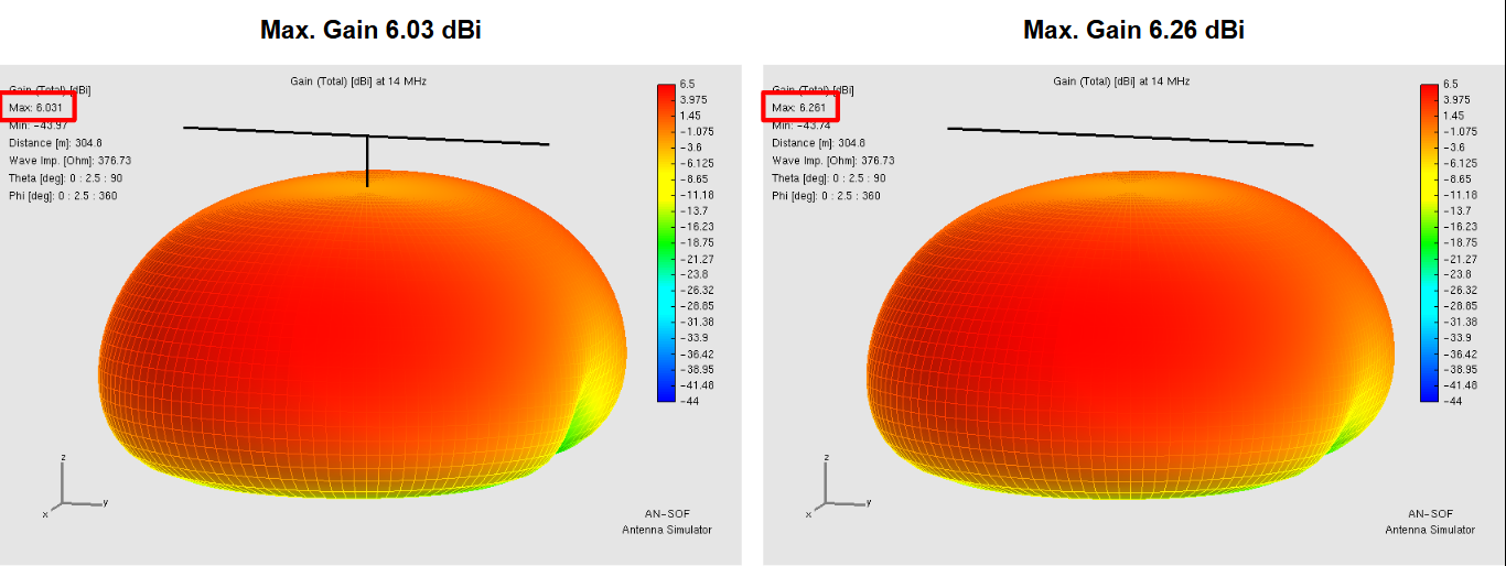
If we plot the 3D radiation pattern of the antenna modeled with and without the coax shield, a slight effect can be observed, as shown in Figure 2, where the gain in dBi is represented with the coax shield on the left and without the coax shield on the right. Removing the coax shield effect in the feeder increases the gain from 6.03 to 6.26 dBi.

The distortion in the radiation pattern is more clearly appreciated in Figure 3, where a slice for Phi = 0° is shown on the left and for Phi = 90° on the right. The blue solid curves represent the gain with the coax shield, and the red dotted curves represent the gain without the coax shield. The coax shield effect is more clearly appreciated in the slice parallel to the dipole (Phi = 90°).
We invite readers to further explore the impact of the coax shield by analyzing its effect on the feedpoint impedance at the source position.
Conclusion
The presented hybrid modeling approach for coaxial transmission lines provides a comprehensive way to account for the external radiation effects caused by common-mode currents. By explicitly modeling the outer surface of the coaxial cable shield, this method enables accurate predictions of potential RF interference, ensuring better performance and reliability of antenna systems. This approach is particularly valuable for RF engineers, ham radio amateurs, and students focused on achieving precision in antenna design and simulation.

