Search for answers or browse our Knowledge Base.
Guides | Models | Validation | Book
An Efficient Approach to Simulating Radiating Towers for Broadcasting Applications
Learn an efficient method to simulate radiating towers for broadcasting applications. This article explores detailed modeling and a simplified approach for analyzing radio mast designs, calculating near-field patterns with minimal effort, and applying these techniques to real-world antenna systems.
Radiating Towers: Applications, Challenges, and the Shift Toward Digital Broadcasting
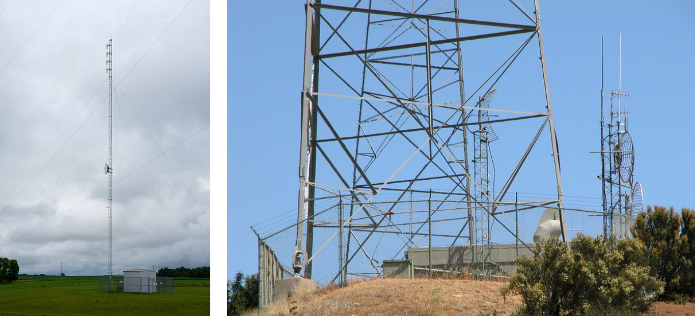
Radiating towers, commonly referred to as base station towers (Fig. 1), are integral to a broad spectrum of frequencies and applications, including:
- Broadcasting: These towers support AM and FM radio transmissions, operating primarily in the low-frequency (LF) to very high-frequency (VHF) ranges.
- Television: TV broadcasting utilizes high-frequency (HF) and ultra-high-frequency (UHF) bands.
- Cellular Communication: Mobile communication towers function across frequencies ranging from 800 MHz to several GHz, encompassing 4G and 5G networks.
- Public Safety Communications: Emergency services, such as police, fire, and medical responders, rely on frequencies within the 25–50 MHz and 150–174 MHz ranges.
- Microwave Links: Operating primarily above 3 GHz, these links enable point-to-point communication.
- Navigation and Radar: Used in maritime and aviation applications, these systems operate within medium to high-frequency bands.
Each of these applications relies on specific frequency bands to optimize performance for its intended purpose.
The Changing Role of Radiating Towers in Broadcasting
The landscape of broadcasting is undergoing significant shifts due to the growing prevalence of internet and streaming services. Traditional AM and FM broadcasting face mounting challenges as audiences increasingly favor digital platforms. Below is a closer look at these trends:
- AM Radio:
AM radio faces the steepest decline due to its lower audio quality compared to FM and digital alternatives. Additionally, it suffers from interference caused by modern devices, such as electromagnetic noise from electric vehicles. While some AM stations are migrating to FM, this transition is limited by regulatory restrictions and available frequencies. - FM Radio:
FM radio remains more resilient but is not immune to competition from streaming services, which provide on-demand and personalized content. FM’s advantages include better audio quality and an established infrastructure, which help maintain its relevance. - Digital Platforms:
Streaming services and internet radio are becoming the preferred options for many listeners due to their personalized experiences and global accessibility. The integration of smart speakers and voice assistants has further enhanced their usability, embedding radio-like experiences into everyday life.
The Future of AM Broadcasting
While AM radio’s decline is pronounced in some regions, it remains vital in rural and remote areas where internet access is limited. For instance, countries like India and parts of Africa still depend on AM broadcasts for delivering news and essential information.
Although AM radio is unlikely to disappear entirely, its prominence is expected to diminish as digital platforms continue to dominate the broadcasting landscape. FM radio may endure longer, but both are evolving to coexist with newer technologies.
Modeling Radiating Towers in AN-SOF: Near-Field Analysis and Ground Wave Propagation
This article outlines key guidelines for effectively modeling radiating towers using AN-SOF. Radio masts, often referred to as radiating towers, can be modeled in AN-SOF with exceptional detail to account for their real-world characteristics.
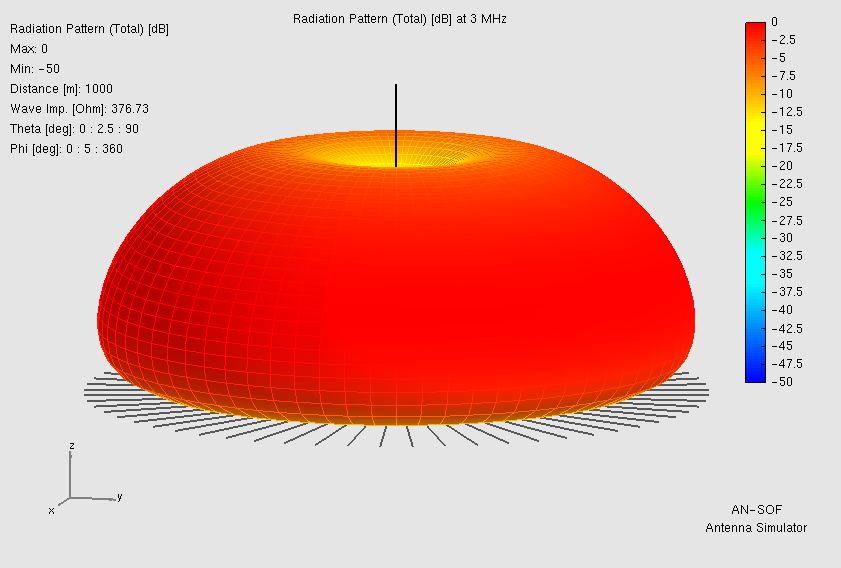
In the low-frequency (LF) and medium-frequency (MF) bands, radio masts function as monopole antennas. These antennas comprise a vertical radiator positioned above a ground plane, with the feedpoint located at the base. A transmission line (feeder) applies voltage between the monopole base and the ground. Monopole antennas are characterized by their omnidirectional radiation pattern in the horizontal plane and vertical polarization (Fig. 2). In the vertical plane, the radiation pattern may feature primary and secondary lobes, depending on the antenna height relative to the operating wavelength.
For ground-level communication, monopole antennas exploit ground wave propagation, which travels along the Earth’s surface. The soil’s conductive properties at low frequencies enhance this propagation, making it an effective mechanism for communication over significant distances.
Near-Field Analysis with AN-SOF
In practical applications, the omnidirectional shape of the radiation pattern in the horizontal plane is well understood. Therefore, the focus shifts to predicting the electric field strength at ground level for a given input power as a function of distance from the monopole base (the so-called ‘surface wave’ analysis).
To achieve accurate predictions, it is advantageous to calculate the near field as a function of distance, avoiding far-field approximations that are only valid at distances of several wavelengths from the antenna. AN-SOF offers three coordinate systems for such analyses: Cartesian, cylindrical, and spherical (Fig. 3). These can be configured as follows:
- Cartesian Coordinates:
- Set Z = 0.
- Vary either the X or Y coordinate, which represent the distance from the antenna in the horizontal plane.
- Cylindrical Coordinates:
- Set Z = 0.
- Fix the azimuth angle Phi and vary the radial distance R from the antenna.
- Spherical Coordinates:
- Set the zenith angle Theta = 90°.
- Fix the azimuth angle Phi and vary the radial distance R.
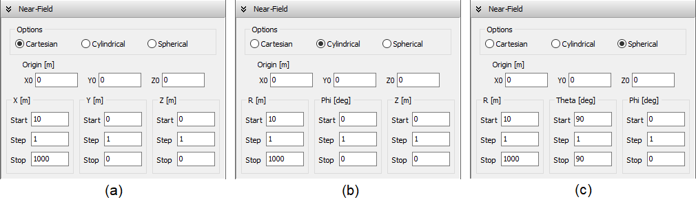
To configure the coordinate system, navigate to the Setup tab > Near-Field panel and select the desired system. Additionally, the Excitation panel allows users to set the input power, where 1 kW (1,000 watts) is commonly used as a reference in broadcasting analyses.
Improving Radiation Efficiency with Ground Screens
To enhance soil conductivity near the antenna and boost radiation efficiency, a radial wire ground screen can be deployed. These conductive screens are crucial for improving the efficiency of radiating towers, particularly when the soil exhibits poor conductivity and a high dielectric constant.
Historically, the design of ground screens was a critical engineering task, receiving significant attention during the peak of AM broadcasting. Properly designed ground screens remain an essential component for ensuring efficient performance in modern systems.
Modeling the Feedpoint and Ground Screen in Monopole Towers
The feedpoint of monopole towers plays a critical role in their performance and requires careful attention during modeling. In practical setups, a base insulator is used to electrically isolate the monopole base from the ground. This allows a transmission line to connect the monopole base and the ground, effectively feeding the antenna.
To simulate this configuration in AN-SOF, you can add a source at the location of the base insulator. By doing so, the model replicates the real-world scenario where the feedline connects at this point. This setup enables the calculation of the antenna’s input impedance. Post-processing can then be applied to determine the input impedance, including the effects of the tuning house and transmission line connected to the transmitter.
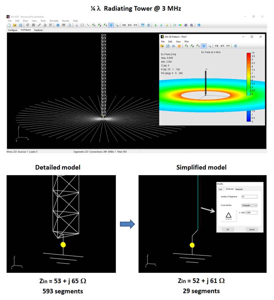
Example Model: A Quarter-Wavelength Radiating Tower
Figure 4 illustrates a quarter-wavelength radiating tower and its electric field pattern at the soil level. In this example:
- Frequency: 3 MHz.
- Soil Properties:
- Conductivity: 0.005 S/m.
- Permittivity (dielectric constant): 13 (typical for average soil in North America).
- Ground Screen:
- 60 radial wires.
- Each wire is 25 meters long (λ/4 at 3 MHz).
This setup models a realistic scenario for a radiating tower. The AN-SOF project files, including precise configuration details, can be downloaded by clicking the button below Fig. 4.

Ease of Modeling in AN-SOF
While creating a model like this might initially seem challenging, AN-SOF’s intuitive drawing functions simplify the process. For step-by-step guidance, watch the accompanying video that demonstrates how to quickly draw a radiating tower.
Optimizing Radiating Tower Models: Simplified vs. Detailed Approaches
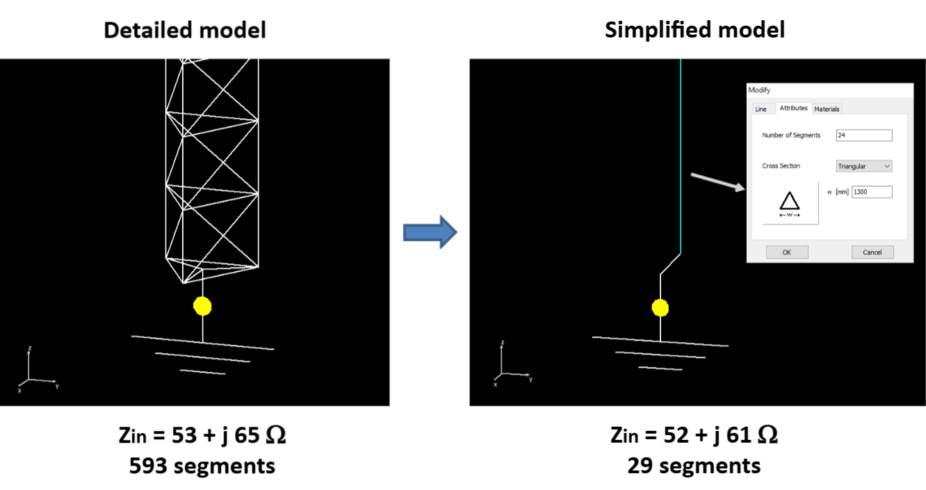
The model shown in Figure 4 consists of:
- 223 wire segments,
- 369 connections between segments, and
- 1 ground point connection,
resulting in a total of 593 electric currents to be solved using the Method of Moments (MoM). The segment count can be conveniently viewed at the bottom of AN-SOF’s interface.
To enhance simulation efficiency, a simplified model can be employed. This approach replaces the intricate details of the tower with a single vertical wire of triangular cross-section. Although this wire represents a solid surface rather than the tower’s structural complexity, its cross-sectional area is negligible compared to the wavelength. This ensures that the simplified model produces an identical radiation pattern to the detailed one. However, regarding input impedance, certain considerations must be made at the feedpoint, as explained below.
Feedpoint Adjustments in Simplified Models
In the detailed model, the base of the tower forms a short transmission line leading to the source at the tower’s center. This short line significantly influences the reactive component of the antenna’s input impedance.
In the simplified model, to replicate this effect:
- Offset the source from the wire’s center by a distance equal to half the tower’s width.
- This adjustment accounts for the short transmission line effect, ensuring accurate input impedance results.
Model Comparison
Figure 5 compares the detailed and simplified models, showcasing the input impedance obtained from each. Key insights:
- The simplified model requires only 29 wire segments, significantly reducing computational complexity.
- Despite the reduced segment count, the results for input impedance, radiation pattern, and antenna efficiency closely match those of the detailed model.
This reduction in complexity makes the simplified model ideal for simulations involving frequency sweeps, where variables like VSWR, radiation pattern, and efficiency need to be evaluated across a range of frequencies.
Applications of Tower Models
Radiating towers are often used as supporting structures for smaller antennas, such as:
- Yagi-Uda arrays or
- Log-Periodic antennas,
operating at higher frequencies.
In these scenarios, the tower model serves as a template that can be imported into another AN-SOF project, simplifying the integration of smaller antennas with the tower. For further insights on project merging in AN-SOF, explore this article: Enhancing Antenna Design Flexibility: Project Merging in AN-SOF.
Conclusions
In this article, we have demonstrated effective approaches to modeling radiating towers in AN-SOF. Radiating towers, essential for low- and medium-frequency communication, function as monopole antennas with unique characteristics that influence their design and simulation. Key takeaways include:
- Detailed Modeling
The intricate structure of a radiating tower can be accurately represented in AN-SOF. By incorporating elements like base insulators, feedlines, and ground screens, it is possible to simulate real-world scenarios with high precision. This approach is invaluable for understanding antenna behavior and optimizing performance metrics such as radiation efficiency and input impedance. - Simplified Modeling for Efficiency
Simplified models, which replace the detailed structure with an equivalent vertical wire, offer a significant reduction in computational requirements. With careful adjustments, such as offsetting the feedpoint to account for the base’s transmission line effect, these models can deliver results nearly identical to those of the detailed approach. This makes them ideal for applications like frequency sweeps, where rapid simulation is crucial. - Practical Applications
Radiating towers not only serve as antennas but also as structural supports for other antenna types, including Yagi-Uda and Log-Periodic arrays. AN-SOF’s modeling tools allow users to create versatile templates that can be integrated into broader antenna systems, facilitating efficient design workflows.
By leveraging both detailed and simplified modeling techniques, engineers and hobbyists alike can achieve accurate, efficient, and insightful simulations of radiating towers. Whether for optimizing standalone towers or incorporating them into complex antenna systems, AN-SOF provides the tools needed to address diverse challenges in antenna design and analysis.
