Search for answers or browse our Knowledge Base.
Guides | Models | Validation | Book
Fractal vs. Arbitrary Geometry: Analyzing the VE9SRB “Random” Loop
Is fractal geometry truly necessary for compact antenna performance? We analyze the VE9SRB ‘Random’ Loop an arbitrarily shaped antenna with the same wire length and aperture as an MI2 Fractal Loop. Using AN-SOF, we demonstrate that while random shapes can achieve comparable gain and impedance, the fractal geometry offers a critical advantage in usable bandwidth.
The “Fractal Advantage” Debate
In fractal antenna theory, it is often argued that the self-similar iterations of a curve (like the Minkowski or Koch fractals) are the key to achieving resonance in a compact aperture. However, an alternative hypothesis suggests that the performance is primarily dictated by two factors: the total wire length and the aperture area.
To test this, we modeled a “Random Loop” designed by radio amateur VE9SRB. This antenna is one of an infinite number of possible non-fractal shapes that maintain the exact same physical constraints as the MI2 Fractal Loop (Snowflake Quad).
Model Geometry and Constraints
To ensure a rigorous comparison, the VE9SRB Loop was modeled in AN-SOF with the following identical parameters to our previously analyzed MI2 loop:
- Total Wire Length: $27.564\text{ m}$
- Physical Aperture: $2.8 \times 2.66\text{ m}$
Unlike the structured iterations of the MI2 fractal, this geometry is arbitrary. This allows us to observe if the electromagnetic “magic” of the fractal is truly unique or if a random shape can provide similar or even superior performance.
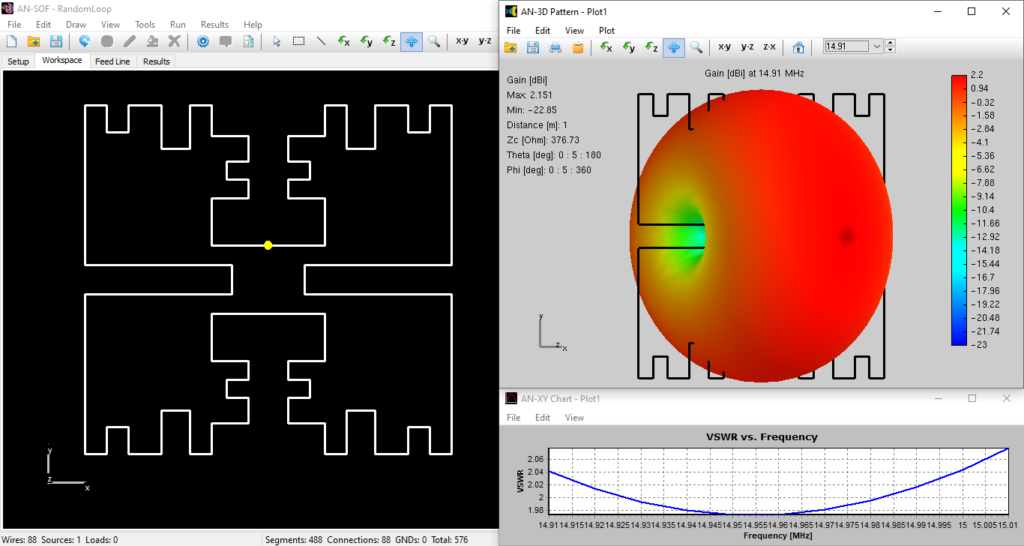
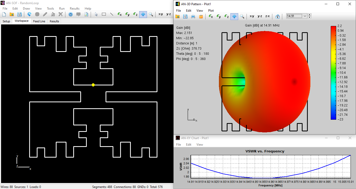
The figure below shows the VE9SRB random loop model in the AN-SOF workspace, the calculated 3D gain pattern in dBi, and the VSWR curve versus frequency. The radiation pattern exhibits the typical donut shape expected for a small loop antenna. The model can be downloaded by clicking the button below the figure.
Comparative Results: Random vs. MI2 Fractal
The AN-SOF simulation reveals that the “Random” geometry behaves as a high-Q resonator, matching several of the MI2’s performance markers but with distinct differences in radiation efficiency and bandwidth.
| Metric | MI2 Fractal Loop | VE9SRB Random Loop |
| Resonant Frequency | $15.335\text{ MHz}$ | $14.95\text{ MHz}$ |
| Input Resistance ($R_{in}$) | $28\ \Omega$ | $25\ \Omega$ |
| Peak Gain | $1.90\text{ dBi}$ | $2.15\text{ dBi}$ |
| 2:1 VSWR Bandwidth | $1.04\%$ | $\sim 0.4\%$ |
1. Resonance and Impedance
The random loop resonates slightly lower ($14.95 \text{ MHz}$) despite having the same wire length. This indicates that the arbitrary distribution of the wire leads to a higher effective inductance or different mutual coupling between segments compared to the ordered MI2 fractal. However, the input resistance remains a very usable $25\ \Omega$, proving that “packing” wire into a small space regardless of the specific pattern successfully raises the radiation resistance of a small loop.
2. Gain and Pattern
Surprisingly, the random loop exhibits a slightly higher gain of $2.15\text{ dBi}$ (compared to $1.90\text{ dBi}$ for the MI2). This suggests that for a single-element radiator, an arbitrary “space-filling” approach can be just as effective at concentrating radiated energy as a formal fractal pattern.
3. The Bandwidth Trade-off
The most significant finding is the Bandwidth. The random loop’s bandwidth is only $0.4\%$, which is significantly narrower than the MI2’s $1.04\%$. In antenna engineering, a narrower bandwidth at a similar size indicates a higher Quality Factor ($Q$). While the random loop is a more “effective” radiator in terms of gain, it is much more sensitive to environmental changes and frequency shifts.
Conclusions
The analysis of the VE9SRB Random Loop provides a vital engineering takeaway: Fractal geometries are not the only way to achieve compact resonance, but they may offer superior bandwidth characteristics. While the random loop achieved a higher gain and a comparable $25\ \Omega$ feedpoint impedance, its extremely narrow bandwidth makes it less practical for real-world applications where frequency agility is required. The MI2 Fractal Loop seems to benefit from its structured iterations by distributing currents in a way that provides a more moderate $Q$ factor. For the antenna designer, this means that while “any” shape can shrink an antenna, the ordered nature of fractals provides a better balance between size reduction and usable bandwidth.
See Also:
Technical Keywords: Compact Antennas, MI2 Fractal Loop, Random Loop Antenna, Antenna Q Factor, Resonant Resistance, Space-Filling Curves, AN-SOF Simulation.
