Search for answers or browse our Knowledge Base.
Guides | Models | Validation | Book
The Lazy-H Antenna: A 10-Meter Band Design Guide
Build a high-performance Lazy-H antenna for the 10-meter band. Learn to design and simulate your own antenna with this guide. Calculate performance with AN-SOF and discover the benefits of wide bandwidth and excellent gain. Watch the included video tutorial for step-by-step modeling.

Introduction
The Lazy-H is a 4-element broadside array which consists of a set of two collinear elements and a set of two parallel elements, all operated in phase to give broadside directivity. Broadside directivity, which focuses the antenna’s energy perpendicular to the antenna elements, is particularly useful for long-distance communication in ham radio applications.
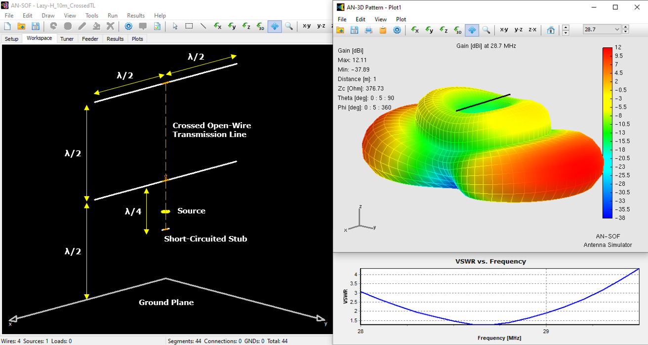
Figure 1 depicts one possible configuration for a Lazy-H array. Antenna elements 1a and 1b are collinear, while elements 2a and 2b are also collinear. Elements 2 are parallel to elements 1 and spaced a distance that can be adjusted to maximize broadside gain. Elements 1 and 2 are connected by means of an open-wire transmission line, so the ‘H’ shape is formed in this way. This H is usually horizontally installed with respect to a flat ground plane and elevated at some convenient height above ground. For installation of the horizontal elements, poles or even nearby trees can be used.

The gain will depend on the spacing, as in the case of a simple parallel element broadside array. The spacing may be chosen between 3/8λ and 3/4λ, while each element is a half-wave dipole (length = λ/2). Estimated gains compared to a single element are:
| Spacing | Gain (dB) |
|---|---|
| 3/8 λ | 4.2 |
| 1/2 λ | 5.8 |
| 5/8 λ | 6.7 |
| 3/4 λ | 6.3 |
Half-wave spacing is generally used, as the example model we will show in this article. The Lazy-H antenna can be fed in several ways. One common method involves connecting a feeder directly to the central open-wire transmission line that connects the elements. Another feeding method, shown in Figure 1, utilizes a reversed or crossed transmission line. Here, precise adjustments are required to ensure the elements and the phasing line are exactly an electrical half wavelength. To achieve a 50-Ohm impedance at the feed point, a quarter-wave short-circuited stub is necessary.
AN-SOF Model and Simulation Results
Figure 2 presents the Lazy-H antenna model within the AN-SOF workspace. Key parameters such as element dimensions, spacing, stub length, and antenna height above ground are explicitly indicated. The upper-right portion of the figure displays the 3D radiation pattern for the 10-meter band, with gain expressed in dBi. The simulated ground plane represents average conditions, characterized by a conductivity of 0.005 S/m and a permittivity of 13. The maximum realized gain is 12 dBi. The VSWR curve as a function of frequency, spanning 28 to 29.5 MHz, is located at the bottom right of Figure 2. A bandwidth of 800 kHz is achieved for a VSWR less than 2, centered around 28.7 MHz. The incorporation of the quarter-wave stub eliminates the need for additional impedance matching networks. The pre-calculated antenna model can be downloaded by clicking the button below Figure 2.

The accompanying video provides a step-by-step tutorial on constructing this Lazy-H design using AN-SOF, including the essential steps of setting up and connecting the transmission lines. As shown in the video, when crossing the wires of a bifilar transmission line to create a phase reversal, a negative characteristic impedance must be entered. This negative sign indicates to the calculation engine that the polarity of the transmission line ends is inverted. The actual characteristic impedance of the line is the absolute value of the entered negative impedance.
Conclusion
The Lazy-H antenna offers a practical and efficient solution for ham radio operators seeking a broadband antenna with a broadside radiation pattern and moderate gain, particularly on the 10-meter band. Its design simplicity and robust performance make it a popular choice for various applications. By leveraging simulation tools like AN-SOF, users can accurately predict antenna characteristics and streamline the design process.
Final Words
We encourage readers to experiment with different element spacings and ground plane conditions to further explore the performance variations of the Lazy-H antenna. By understanding the fundamental principles and utilizing advanced simulation software, you can confidently design and construct your own custom antenna systems.

