Search for answers or browse our Knowledge Base.
Guides | Models | Validation | Book
Beyond NEC: Accurate LF/MF Grounding with the James R. Wait Model
Discover the competitive advantage of AN-SOF’s exclusive James R. Wait ground model. This guide explores how to accurately simulate LF/MF broadcast masts with radial wire ground screens, allowing for direct wire-to-ground connections, a critical feature for realistic impedance and efficiency calculations that legacy NEC-based solvers cannot match.
Accurately calculating the power dissipated in the soil is essential for determining the radiation efficiency of monopole antennas and broadcast towers. AN-SOF incorporates a specialized ground model based on the theory developed by James R. Wait, specifically designed to account for ground losses in the LF (Low Frequency) and MF (Medium Frequency) bands.
The Importance of Ground Screens
Within the LF/MF spectrum, the earth serves as a lossy return path for antenna currents. To mitigate high ground resistance and maximize radiation efficiency, a ground screen is typically installed (Fig. 1). This system consists of buried radial wires that provide a low-impedance path for return currents. Without an accurate mathematical model of this screen-soil interaction, simulation results often overestimate antenna gain and underestimate the required transmitter power.
The Wait Ground Model Advantage
While most electromagnetic solvers rely on the Reflection Coefficient Method (RCM) or the Sommerfeld-Norton model, these approaches have significant limitations for broadcast engineering:
- Sommerfeld-Norton: Extremely accurate for antennas above ground but does not allow for wires to be electrically connected to the ground plane.
- Wait’s Model: Utilizes surface impedance theory to allow for direct wire-to-ground connections. This is critical for modeling monopoles, shunt-fed towers, and any structure where the radiator is physically bonded to the ground system.
AN-SOF is the only simulation software of its kind to offer this unique implementation alongside standard PEC, RCM, and Sommerfeld-Norton models, providing a comprehensive toolkit for broadcast antenna design.
Simulation Case Study: 1/4 Wave Tower
To demonstrate the precision of the Wait implementation, a validation simulation was performed using a standard broadcast configuration:
- Frequency: $3 \text{ MHz}$ (wavelength $\lambda \approx 100 \text{ m}$).
- Antenna Height: $1/4$ wavelength tower.
- Ground System: $60$ radial wires.
- Soil Parameters: Average soil (Conductivity $\sigma = 0.005 \text{ S/m}$, Dielectric Constant $\varepsilon_r = 13$).
- Input Power: $1 \text{ kW}$.
The simulation tracks the Electric Field (E-field) intensity as a function of distance from the tower. By incorporating the Wait theory, AN-SOF accounts for the transition from the high-conductivity radial zone to the lossy soil beyond the screen, providing a realistic assessment of the “ground wave” propagation and the actual power delivered to the far-field.
Simulation Results and Performance Analysis
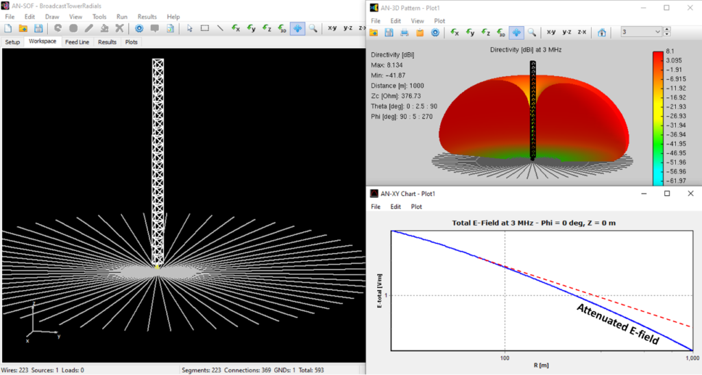
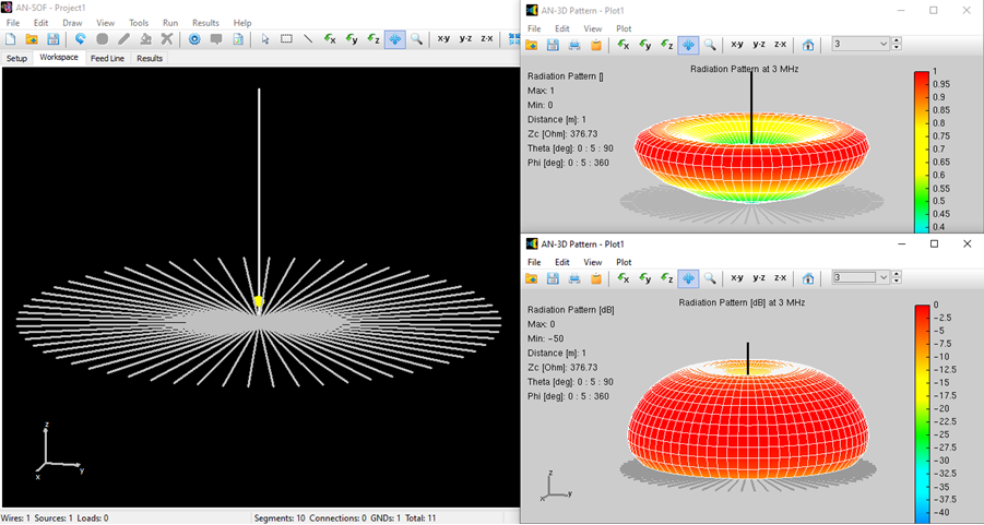
Figure 2 illustrates the $\lambda/4$ radiating tower model within the AN-SOF workspace, featuring the radial wire ground screen centered at the base. The results include both the far-field radiation pattern and a plot of the E-field intensity at soil level as a function of distance.
The far-field radiation pattern displays the characteristic toroidal (“donut”) shape, with a sharp null along the tower’s vertical axis. In this far-field representation, the field is also null at soil level; this occurs because the space wave is the primary component modeled in the far region, whereas the ground wave has effectively attenuated to zero at these extreme distances.

Because broadcast coverage relies on receivers at ground level, evaluating the E-field at soil level is critical. The plot in Fig. 2 compares two distinct scenarios:
- The Red Dashed Line: Represents the theoretical unattenuated case over a Perfect Electric Conductor (PEC).
- The Solid Blue Curve: Represents the actual lossy ground conditions calculated using Wait’s theory.
By comparing these curves, users can visualize the significant ground wave attenuation occurring between $100 \text{ m}$ (one wavelength) and $1 \text{ km}$. This analysis provides the necessary data to determine radiation efficiency and ensures that the transmitter power is sufficient to overcome environmental ground losses.
How to Activate the Wait Ground Model
To utilize James R. Wait’s theory for your LF/MF designs, follow these steps in the AN-SOF workspace:
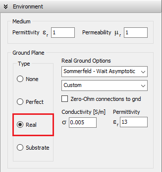
- Navigate to the Setup tab and select the Environment panel (Fig. 3).
- In the Ground Plane section, change the type from “None” or “Perfect” to Real.
- Locate the model selection dropdown and choose either:
- Sommerfeld-Wait/Asymptotic
- Radial wire ground screen (for explicit screen modeling).
- Input the specific conductivity and permittivity of your site’s soil.
By selecting these options, the engine applies the appropriate surface impedance calculations to the ground interface, ensuring that your efficiency, gain, and input impedance results reflect real-world environmental losses.
Comparative Analysis: AN-SOF vs. NEC Ground Models
To conclude this validation, it is helpful to compare the ground modeling capabilities of AN-SOF against legacy codes like NEC-4 and NEC-5. While both tools offer basic real-ground implementations, AN-SOF provides a more comprehensive suite of models specifically tailored for LF/MF broadcast engineering and complex ground-wire interactions.
| Ground Model | AN-SOF | NEC-4/5 |
|---|---|---|
| Perfect Ground (PEC) | Yes | Yes |
| Sommerfeld – Norton | Yes | Yes |
| Sommerfeld – Wait | Yes | No |
| Reflection Coefficients | Yes | Yes |
| Radial Wire Ground Screen | Yes (+) | Yes (−) |
| Dielectric Substrate | Yes | No |
Technical Notes on Model Differences
- (+) AN-SOF Implementation: AN-SOF utilizes the Sommerfeld–Wait ground model to compute ground losses in direct combination with the surface impedance of the wire screen. This advanced approach provides highly accurate input impedance for monopoles and broadcast towers, and is valid for both near-field and far-field calculations.
- (−) NEC Implementation: NEC approximates wire screens using the Reflection Coefficient Method (RCM). Under this model, the calculated input impedance of a monopole is identical to that of an antenna over a Perfect Electrical Conductor (PEC), failing to account for physical ground resistance at the feed point. Consequently, this model is only valid for far-field gain approximations.
- Ground Connections: Unlike NEC, AN-SOF allows for explicit wire connections to ground with either user-defined ohmic losses or as zero-ohm ideal connections. This flexibility is available in both the Sommerfeld–Wait and Radial Wire Ground Screen models, making it the superior choice for modeling grounded structures and lightning protection systems.
Interactive Ground Model Selection Tools
To assist in selecting the appropriate real ground model, you can access the Loss Tangent Calculator and Ground Plane Selector here:
Who was James R. Wait?
James R. Wait was a Canadian engineer known for his academic qualifications and prolific contributions to electromagnetic propagation engineering. He was elected as a member of the National Academy of Engineering in 1977 and authored numerous papers and books. Born in Ottawa in 1924, Wait received his BS and MS in engineering physics and his PhD in electrical engineering from the University of Toronto. He held various research positions worldwide and became a professor at the University of Arizona. Those interested in learning more about Wait’s life may refer to the article “James R. Wait—Remarkable Scientist” by Ernest K. Smith, IEEE Transactions on Antennas and Propagation, Vol. 48, No. 9, pages 1278-1286, September 2000″.
Conclusions
The integration of James R. Wait’s theory into AN-SOF represents a significant advancement for broadcast engineers working in the LF and MF bands. By moving beyond the limitations of the Reflection Coefficient Method used in legacy codes like NEC, AN-SOF provides a physically consistent model where wire-to-ground connections are explicitly accounted for.
As demonstrated in the 3 MHz tower case study, the ability to simulate the transition from a high-conductivity ground screen to lossy soil is vital for predicting real-world performance. This ensures that calculated parameters, such as the 1 kW E-field coverage and the input impedance of grounded towers, reflect the actual environmental losses encountered in the field. Ultimately, the use of the Sommerfeld-Wait model allows for more reliable link budget analysis and more efficient ground screen designs, ensuring that regulatory compliance and coverage goals are met with confidence.
See Also:
Technical Keywords: James R. Wait Theory, LF/MF Broadcast Antennas, Ground Loss Calculation, Radial Wire Ground Screen, Sommerfeld-Wait Model, Ground Wave Attenuation, Monopole Efficiency, Surface Impedance, Input Impedance Convergence, Radio Mast Simulation, Broadcast Engineering, E-Field coverage.
