Search for answers or browse our Knowledge Base.
Guides | Models | Validation | Book
Exploring an HF Log-Periodic Sawtooth Array: Insights from Geometry to Simulation
This article explores the design and analysis of log-periodic sawtooth arrays (LPSA) for HF communications. It covers their geometric principles, frequency-independent characteristics, and demonstrates how AN-SOF simulation software models these antennas, providing valuable insights into their performance and behavior.

Introduction: The Evolution of Log-Periodic Antennas in HF Communication
The demand for antenna systems with consistent radiation patterns and input impedance characteristics across a wide frequency range has driven the development of log-periodic antenna arrays. These arrays, whose foundational advancements and applications date back to the 1950s, have become essential in high-frequency (HF) communication. Given that the upper limit of HF bands is 30 MHz, corresponding to wavelengths exceeding 10 meters, log-periodic arrays for this range are inherently large, often spanning several meters or even tens of meters.
Historically, the Collins Radio Company played a significant role in the development and commercialization of these antennas. They offered three primary configurations: Trapezoidal Tooth, Triangular Tooth, and Dipole Array, as illustrated in Fig. 1.

Collins Radio Company, founded in 1933 by Arthur A. Collins in Cedar Rapids, Iowa, USA, specialized in designing and manufacturing shortwave and AM radio equipment for military, scientific, and commercial applications. After experiencing financial challenges, the company was acquired by Rockwell International in 1973, becoming Rockwell Collins, Inc. In 2001, the avionics division of Rockwell International was spun off, retaining the Rockwell Collins name. Eventually, the company became part of Collins Aerospace following its acquisition by United Technologies Corporation (now RTX Corporation) on November 27, 2018.
Key Design Requirements for HF Antennas
Antennas intended for HF circuits must perform effectively across a broad frequency range. This performance encompasses maintaining both a consistent radiation pattern and a proper impedance match to the designated transmission line. Additionally, HF antennas should be optimized to use the most effective vertical angles while suppressing others that can introduce multipath delays and signal distortion.
The radiation pattern must exhibit low sidelobes to minimize interference at the receive site and prevent the antenna from causing interference with other stations during transmission. Maximizing the antenna’s gain, within the constraints of the installation site, is another critical design objective.
Beyond these general requirements, factors such as polarization and propagation must also be carefully considered. These considerations are especially significant in ground wave propagation at the surface level and sky wave propagation through ionospheric layers. However, a detailed discussion of these topics is beyond the scope of this article and will be addressed in a future publication.
Log-Periodic Antennas: Geometry and Design Principles
As previously highlighted, HF communication systems require antenna designs with radiation patterns and input impedance characteristics that remain essentially independent of frequency. During the 1950s, the first log-periodic antennas emerged, offering both geometric simplicity and consistent radiation and impedance properties in free space. Collins Radio Company played a pioneering role in their development, designing various log-periodic configurations tailored for specific applications.
The geometry of log-periodic antennas is carefully crafted so that their electrical properties repeat periodically with the logarithm of the operating frequency. To achieve frequency independence, the variation of these properties over one logarithmic period is kept minimal, ensuring consistency across all periods.
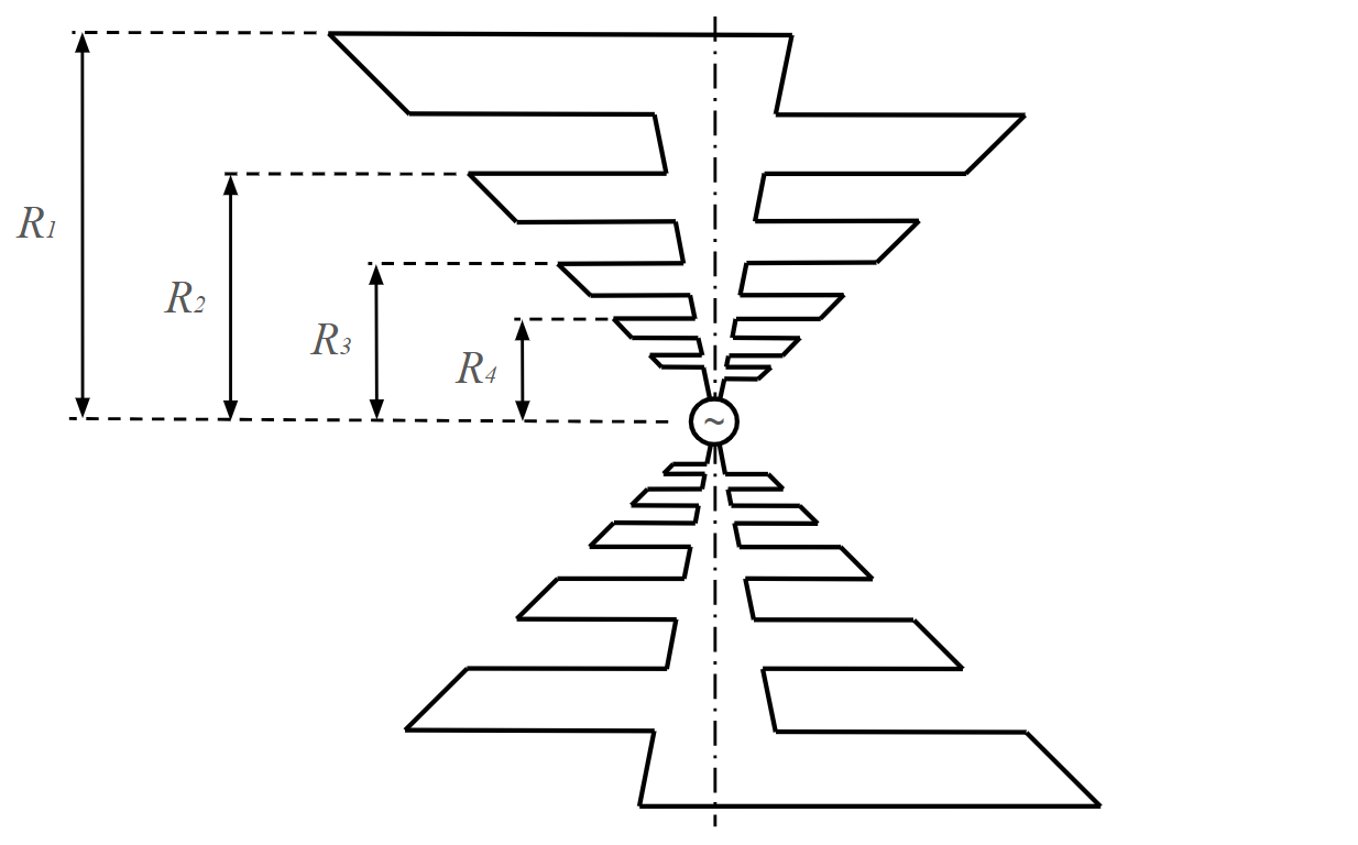
This design principle is demonstrated in Figure 2, which depicts a metal-sheet log-periodic structure with trapezoidal teeth. In this configuration, two symmetrical halves are fed in opposition by a generator located between their vertices. The logarithmic principle mandates that dimensions such as $R_1$, $R_2$, $R_3$, and so forth, form a geometric sequence with a constant ratio $\tau$, defined as:
$\displaystyle \tau = \frac{R_2}{R_1} = \frac{R_3}{R_2} = \frac{R_4}{R_3} = … = \frac{R_{n+1}}{R_n}$

Consider designing the antenna shown in Figure 2 to operate effectively at a specific frequency $f_n$. To achieve this, the ratio of successive dimensions, $R_{n+1}/R_n$, is maintained as a constant $\tau$. If the antenna radiates efficiently at frequency $f_n$, primarily due to the element $R_n$, it will also radiate at frequencies $f_{n-1}$ and $f_{n+1}$. This is because the antenna structure exhibits electrical equivalence to wavelengths $\lambda_n = c/f_n$, $\lambda_{n-1} = c/f_{n-1}$, and $\lambda_{n+1} = c/f_{n+1}$, where $c$ represents the speed of light.
As a result, if the antenna radiates at $f_n$, it will radiate at all frequencies that are constant multiples of $f_n$, expressed as:
$\displaystyle \ldots, \, \frac{f_n}{\tau^2}, \, \frac{f_n}{\tau}, \, f_n, \, \tau f_n, \, \tau^2 f_n, \, \ldots$
This periodicity is achieved by designing a structure that geometrically repeats itself with a consistently increasing multiplicative factor, the geometric ratio $\tau$. Consequently, if the antenna radiates at a specific frequency, it will radiate at all frequencies that are multiples of $\tau$.
Exploring the Log-Periodic Sawtooth Array Model
Log-periodic antenna structures come in an infinite variety of configurations. The three examples shown in Figure 1 illustrate wire-based log-periodic designs: trapezoidal teeth, triangular teeth, and the dipole array (LPDA). The LPDA can be viewed as a simplified version of the trapezoidal structure, where the thickness of the teeth and metal sheets is reduced to zero, along with the angle between the two symmetrical halves. Despite these differences, all these structures exhibit comparable radiation patterns and impedance characteristics.
In these designs, radiation primarily results from currents flowing through the “teeth,” producing a polarization that is transverse to the centerline of the half structure. Each design consists of two symmetrical halves, forming a balanced antenna.
For balanced operation, the antenna can be fed using a two-wire transmission line, with the wires connected to the vertices of the half structures. Careful placement minimizes distortion of the radiation pattern. In unidirectional configurations, the transmission line is typically aligned with the bisector of the centerlines of the two halves. Alternatively, the antenna can be fed with a coaxial cable, where the cable runs along the centerline of one half structure and is bonded to it. To maintain balance, a dummy cable is often added to the other half structure, effectively creating a frequency-independent balun.
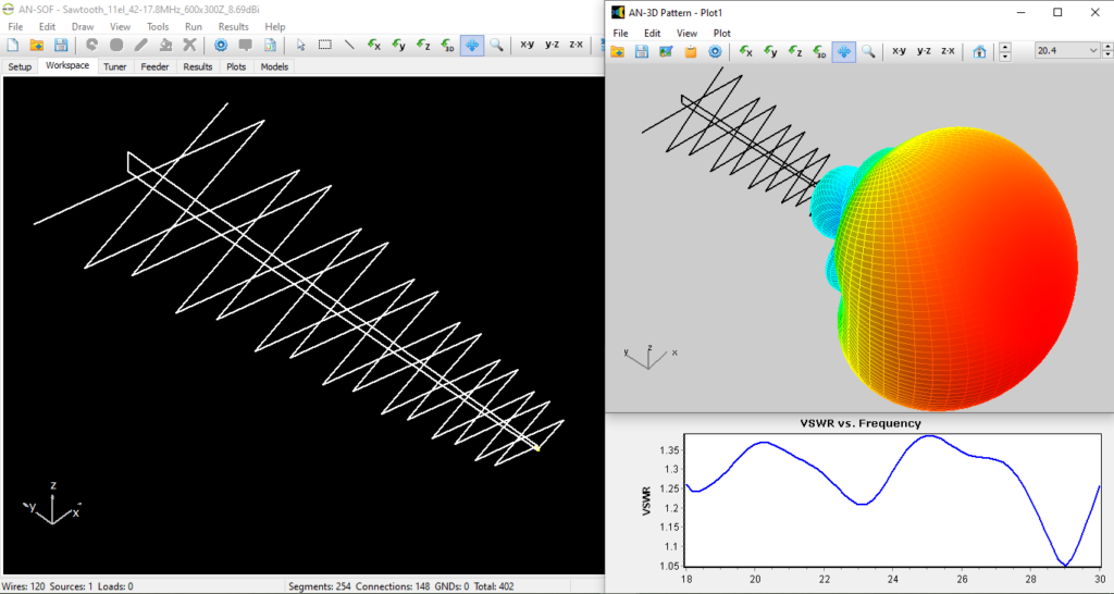
This section highlights a Log-Periodic Sawtooth Array (LPSA) design similar to the configuration depicted in Figure 1(b). These large LPSAs are typically constructed using tethers and continue to serve as reliable point-to-point communication antennas for military bases. AN-SOF proves to be an excellent tool for modeling LPSAs, particularly due to its ability to handle acute angles with precision.
The model and results showcased in Figure 3 were generously contributed by Ĝan Ŭesli Starling (KY8D, M0KYD, VA7KYD, ZD7KYD, and ZS1KYD, https://ky8d.net/). We extend our gratitude to Ĝan for sharing this design and highlighting the importance of accurately modeling acute angles—a task where AN-SOF excels thanks to its Conformal Method of Moments with Exact Kernel.

Ĝan’s feedback underscores AN-SOF’s efficacy in simulating this unique design. Figure 3 displays the antenna model within AN-SOF’s workspace, featuring 14 teeth and spanning a frequency range from 18 to 30 MHz. The total antenna length is approximately 18 meters. Precise dimensions and tooth angles are crucial for constructing this design and can be accessed by downloading the model via the button below Figure 3.
The radiation pattern for this model exhibits a gain between 9 and 9.6 dBi across the specified frequency range. The VSWR remains below 1.4, with minima of 1.2 and 1.05. The VSWR is calculated at the feeder input rather than at the antenna terminals. The feeder used is a 1-meter-long LMR-400 TMS line, with a characteristic impedance of 50 Ohms and a velocity factor of 0.85. Line losses are incorporated using a matched loss curve derived from the cable datasheet. These parameters are automatically configured by selecting the LMR-400 TMS cable type in AN-SOF’s Feeder tab.
Additionally, a 1:4 balun transformer connects the antenna terminals to the feeder, effectively reducing the feedpoint impedance. The input power for this model is set to 100 W. While this power level does not influence gain or VSWR results, it factors into feeder loss calculations, enabling users to determine the exact power loss within the cable.
Figure 4 presents an animation of the 3D radiation pattern as a function of frequency. It reveals that while the main lobe remains almost constant, the secondary lobes exhibit significantly more variation. We encourage users to explore the Plots tab in AN-SOF to analyze the Front-to-Rear (F/R) and Front-to-Back (F/B) ratios. These ratios, which can be visualized in both the vertical (V) and horizontal (H) planes, demonstrate variations ranging from approximately 20 to 40 dB. Such insights underscore a key challenge in designing log-periodic antennas: managing the behavior of secondary lobes across a wide frequency range.

Figure 5 displays an animation of the current distribution along the analyzed LPSA, varying with frequency. The animation illustrates an active sector comprising approximately three elements, which moves along the antenna as the frequency increases, from the longest element to the shortest. These active elements are primarily responsible for radiation at any given frequency, while the remaining elements act as passive structures with negligible contribution to the main lobe. This phenomenon is characteristic of all log-periodic arrays and stems directly from their inherent log-periodicity.

Conclusions
Log-periodic antennas, with their unique geometric and electrical properties, remain an indispensable tool in high-frequency communications. Their ability to maintain consistent radiation patterns and impedance characteristics over a wide frequency range makes them particularly well-suited for applications requiring frequency agility and reliability. The exploration of the Log-Periodic Sawtooth Array (LPSA) has highlighted the practical benefits of this design, including its ability to achieve high gain, low VSWR, and stable radiation performance.
The insights provided by AN-SOF, as demonstrated in this article, further emphasize the importance of accurate modeling and simulation in antenna design. The software’s capability to handle complex structures, such as acute angles and intricate feed systems, has proven invaluable for analyzing and optimizing LPSAs. Additionally, the animations of radiation patterns and current distributions shed light on critical design considerations, such as the management of secondary lobes and the role of active elements.
This study reaffirms the importance of log-periodic arrays in modern communication systems and encourages further innovation in their design and implementation.

