Search for answers or browse our Knowledge Base.
Guides | Models | Validation | Book
RF Techniques: Implicit Modeling and Equivalent Circuits for Baluns
Explore how AN-SOF simplifies the process of modeling transformers and baluns with implicit techniques. Learn to transform antenna impedance using equivalent circuits. A must-read for engineers and RF enthusiasts!
Introduction
One effective way to transform the input impedance of an antenna for tuning or achieving impedance matching is by adding a transformer. When the transformer serves as an interface between a balanced system and an unbalanced system, it is called a BALUN (Balanced to Unbalanced transformer). Baluns are used to interface balanced transmission lines (e.g., open-wire lines used with dipole antennas) with unbalanced systems (e.g., coaxial cables). Baluns help ensure impedance matching, reduce common-mode currents, and prevent radiation from the feed line. There are several types: Transformer (Voltage, Current, Impedance), Transmission Line balun, Guanella balun (1:4, 1:9, etc.), and Ruthroff balun. Additionally, there are UNUNs (unbalanced to unbalanced transformers).
This article presents a quick method to simulate the presence of a lossless transformer balun connected to the terminals of an antenna. We will demonstrate how to set up an equivalent circuit for the balun in AN-SOF Antenna Simulator.
Modeling Transformers with Two-Port Networks
Figure 1(a) shows the circuit model of a voltage transformer, where $n$ is the winding ratio (primary to secondary winding number of turns). A small resistance $R$ has been added in series with the primary and secondary windings to model all kinds of losses inside the transformer. However, this resistance will be later neglected to simplify calculations. Therefore, the voltages $V_1$ and $V_2$ are related by:
$\displaystyle V_1 = n \, V_2 \qquad (1)$

Figure 1(b) shows the equivalent two-port network for the transformer, represented by its admittance matrix $[Y]$, which is given by:
$[Y] = \begin{bmatrix}
\displaystyle \frac{G}{n^2} & \displaystyle -\frac{G}{n} \\
\displaystyle -\frac{G}{n} & \displaystyle G
\end{bmatrix} \qquad (2)$
where $G =1/R$. Note that we cannot neglect $R$ in this step ($R \rightarrow 0$) since the admittance matrix would become infinite. Consequently, the set of two equations relating the currents $I_1$ and $I_2$ at the network ports 1 and 2, and the voltages $V_1$ and $V_2$ are the following:
$\displaystyle I_1 = \frac{G}{n^2} \, V_1 \,\,\, – \,\,\, \frac{G}{n} \, V_2 \qquad (3)$
$\displaystyle I_2 = -\frac{G}{n} \, V_1 \, + \, G \, V_2 \qquad (4)$
It is easy to show that when both ports are open-circuited ($I_1 = I_2 = 0$), equation (1) is readily derived from (3) and (4). Therefore, the primary to secondary voltage ratio, $n$, is embedded in the transformer network model.
Antenna Input Impedance with Connected Transformers
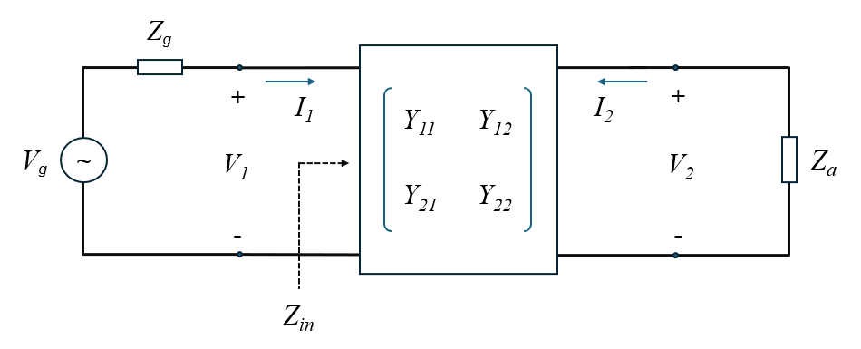
Let’s consider the circuit depicted in Figure 2, where a voltage source with applied voltage $V_g$ and internal impedance $Z_g$ is connected to the transformer input port, and a load impedance $Z_a$ is connected to the transformer output port. $Z_a$ represents the impedance seen at the antenna terminals, essentially the antenna’s input impedance. We want to calculate the input impedance $Z_{in}$ at the transformer input port given $Z_a$.

Note that:
$\displaystyle Z_{in} = \frac{V_1}{I_1} \qquad (5)$
$\displaystyle Z_a = \frac{V_2}{-I_2} \qquad (6)$
By working with equations (3), (4), and (6), it is easy to solve for $Z_{in}$, which is given by:
$\displaystyle Z_{in} = n^2 \, (R \, + \, Z_a) \qquad (7)$
Now, we can neglect the loss resistance ($R = 0$), to find that the input impedance for a lossless transformer is obtained by multiplying the antenna impedance by the square of the winding ratio. Therefore, the impedance transformation factor is defined as $K = 1/n^2$. Practical baluns are specified by their impedance transformation factor $K$ (referred to as a $1:K$ balun) instead of the winding ratio. Therefore, for a lossless balun, we have:
$\displaystyle Z_{in} = \frac{Z_a}{K} \qquad (8)$
When transformer losses cannot be neglected, AN-SOF provides a model that includes them via an insertion loss parameter in decibels, which can be found in the Tuner and Feeder tabs of the program.
The reflection coefficient obtained from the input impedance (8) seen at the transformer port 1 is given by:
$\displaystyle \rho_1 = \frac{Z_{in} \,\, – \,\, Z_g}{Z_{in} + Z_g} = \frac{Z_a \,\, – \,\, K \, Z_g}{Z_a + K \, Z_g} \qquad (9)$
Where $Z_g$ is used as the reference impedance, as it is the generator’s internal impedance (commonly $Z_g$ = 50 or 75 Ohms in RF applications).
Then, the VSWR at port 1 is given by:
$\displaystyle VSWR_1 = \frac{1 + \rho_1}{1 \,\, – \,\, \rho_1} \qquad (10)$
Our objective in the next section is to find an equivalent circuit where only the impedance transformation factor $K$ plays a role, avoiding the need to explicitly model the transformer.
Thévenin’s Equivalent Circuit for Transformers
We now want to replace the system composed of the voltage source connected to the transformer shown in Figure 2 with its Thévenin equivalent circuit. This requires calculating the open circuit voltage ($V_{oc}$) and the short-circuit current ($I_{sc}$) at port 2, namely:
$\displaystyle V_{oc} = V_2 \, \bigg|_{I_2 \, = \, 0} \qquad (11)$
$\displaystyle I_{sc} = I_2 \, \bigg|_{V_2 \, = \, 0} \qquad (12)$
Then, the whole system shown in Figure 2 can be replaced by the equivalent circuit shown in Figure 3.

Note that, at port 1 in Figure 2, the current is given by (regardless if port 2 is open or short-circuited):
$\displaystyle I_1 = \frac{V_g \,\, – \,\, V_1}{Z_g} \qquad (13)$
When port 2 is open-circuited ($I_2 = 0$), we have $V_1 = n \, V_2$, and by inserting (13) into (3), we can solve for $V_2 = V_{oc}$ to obtain:
$\displaystyle V_{eq} = V_{oc} = \frac{V_g}{n} \qquad (14)$
Beautiful result! The Thévenin’s generator voltage is just the true generator voltage transformed by $n$.
By inserting $V_2 = 0$ in (3) and (4), we obtain $I_2 = I_{sc} = – V_1 \, G/n$ and $I_1 = V_1 \, G/n^2$. Using (13), we can obtain the $V_g/V_1$ ratio and express $I_{sc}$ in terms of $V_g$ and $Z_g$. After these straightforward calculations, we obtain the internal impedance of the equivalent generator as:
$\displaystyle Z_{eq} = \frac{V_{oc}}{I_{sc}} = R + \frac{Z_g}{n^2} \qquad (15)$
For a lossless transformer ($R = 0$) and using the impedance transformation factor, $K = 1/n^2$, we have:
$\displaystyle Z_{eq} = K \, Z_g \qquad (16)$
and (14) can be rewritten as:
$\displaystyle V_{eq} = \sqrt{K} \, V_g \qquad (17)$
Now, we have to calculate the reflection coefficient at the antenna terminals, $\rho_2$, and the corresponding VSWR, which are given by:
$\displaystyle \rho_2 = \frac{Z_a \,\, – \,\, Z_{eq}}{Z_a + Z_{eq}} = \frac{Z_a \,\, – \,\, K \, Z_g}{Z_a + K \, Z_g} \qquad (18)$
$\displaystyle {VSWR}_{2} = \frac{1 + \rho_2}{1 \,\, – \,\, \rho_2} \qquad (19)$
Finally, comparing these equations with (9) and (10), we have:
$\displaystyle \rho_2 = \rho_1 \qquad (20)$
$\displaystyle VSWR_2 = VSWR_1 \qquad (21)$
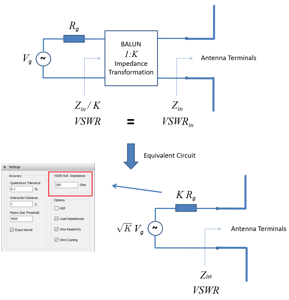
Note that the internal impedance of the equivalent generator has been used in (18) to obtain the reflection coefficient. This result shows that to obtain the same VSWR at the input port of the transformer connected to the antenna, we simply have to use the internal impedance of the true generator multiplied by $K$, the transformer impedance factor, as the reference impedance for the VSWR. Furthermore, to replicate the voltage and current values at the antenna terminals, we can remove the transformer and add an equivalent generator with an applied voltage $\sqrt{K} \, V_g$ and internal impedance $K \, Z_g$, where $V_g$ and $Z_g$ are the voltage and internal impedance of the true generator, respectively.
How to use this straightforward model in AN-SOF is explained in the next section.
Using AN-SOF for Implicit Transformer Modeling
As we have derived in the previous sections, a balun or impedance transformer with factor $K$ can be implicitly modeled using an equivalent generator. Since voltage sources in AN-SOF can have an internal impedance, we can adjust the internal resistance value by multiplying it by $K$ to match the antenna input resistance, effectively connecting a $1:K$ impedance transformer at the antenna terminals. It is important to first cancel out the antenna reactance using an opposite lumped reactance.
To have AN-SOF calculate the VSWR at the true generator side, go to the Setup tab > Settings panel > VSWR Ref. Impedance, and set it to the same value as the internal impedance of the equivalent circuit of the transformer: $K \, Z_g$. If the true voltage and current values are required at the antenna terminals, adjust the source voltage to $\sqrt{K} \, V_g$ and its internal impedance to $K \, Z_g$.
For example, if we connect a $1:4$ balun ($K = 4$) to reduce an impedance of 300 Ohms to 75 Ohms, connect a voltage source at the antenna terminals with $2$ times the voltage of the true source and an internal impedance of $4$ times the true internal impedance (4 x 75 = 300 Ohms). Then, enter the reference impedance for VSWR in the Settings panel as $4$ times the true internal impedance (300 Ohms).
Figure 4 illustrates the procedure to configure the balun equivalent circuit in AN-SOF.

Conclusions
This article has illustrated how AN-SOF streamlines the modeling of transformers and baluns using implicit techniques. By employing equivalent circuits, we can rapidly transform antenna impedance and expedite the design process. The VSWR at the transformer input can be predicted by simply adjusting the reference impedance in the reflection coefficient formula calculated at the antenna terminals. This method allows us to design and analyze antenna systems quickly and accurately. AN-SOF’s approach significantly reduces the time and effort required for antenna modeling, enabling users to achieve precise results with greater ease.

